Smart home monitoring device

A monitoring device and smart home technology, applied in the direction of TV, color TV, supporting machine, etc., can solve the problems of poor installation effect, hidden safety hazards, troublesome cleaning process, etc., to reduce manual operation, improve safety, and fast cleaning speed. Effect

Active Publication Date: 2020-10-13
广州狸园科技有限公司
View PDF22 Cites 3 Cited by
  • Summary
  • Abstract
  • Description
  • Claims
  • Application Information

AI Technical Summary

Problems solved by technology

[0003] During the use of the existing smart home monitoring device, because the camera of the monitoring device is installed on the top of the corner of the room, dust is easy to breed in the corner. As the monitoring device is used longer and longer, the dust in the air in the room gradually Covering the camera of the monitoring device makes the video screen recorded by the camera have a gray fog effect, which reduces the recording clarity and the monitoring shooting effect of the camera, and the cleaning process is more troublesome, due to the installation position of the monitoring device It is relatively high, and it is necessary to stand on a high place with the help of a ladder for cleaning. There are potential safety hazards during the cleaning process, and the cleaners are prone to fall incidents, which makes the cleaning effect of the existing monitoring device poor and poor in use
[0004] In addition, during the use of the existing smart home monitoring device, since the monitoring device needs to have a wide recording angle, it is necessary to install the monitoring device in a suitable position, that is, to install the monitoring device on the top surface of the ceiling of the house. It is relatively high, and it is necessary to manually carry the installation equipment and complete the nailing work on the ladder during installation. The nai

Method used


Image

  • Smart home monitoring device
  • Smart home monitoring device
  • Smart home monitoring device

Examples


Example Embodiment

[0038] The technical solutions in the embodiments of the present invention will be clearly and completely described below in conjunction with the accompanying drawings in the embodiments of the present invention. Obviously, the described embodiments are only a part of the embodiments of the present invention, rather than all the embodiments. Based on the embodiments of the present invention, all other embodiments obtained by those of ordinary skill in the art without creative work shall fall within the protection scope of the present invention.
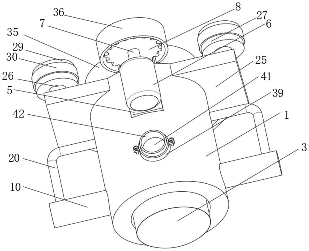
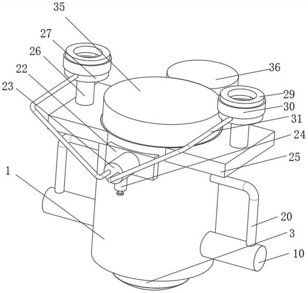
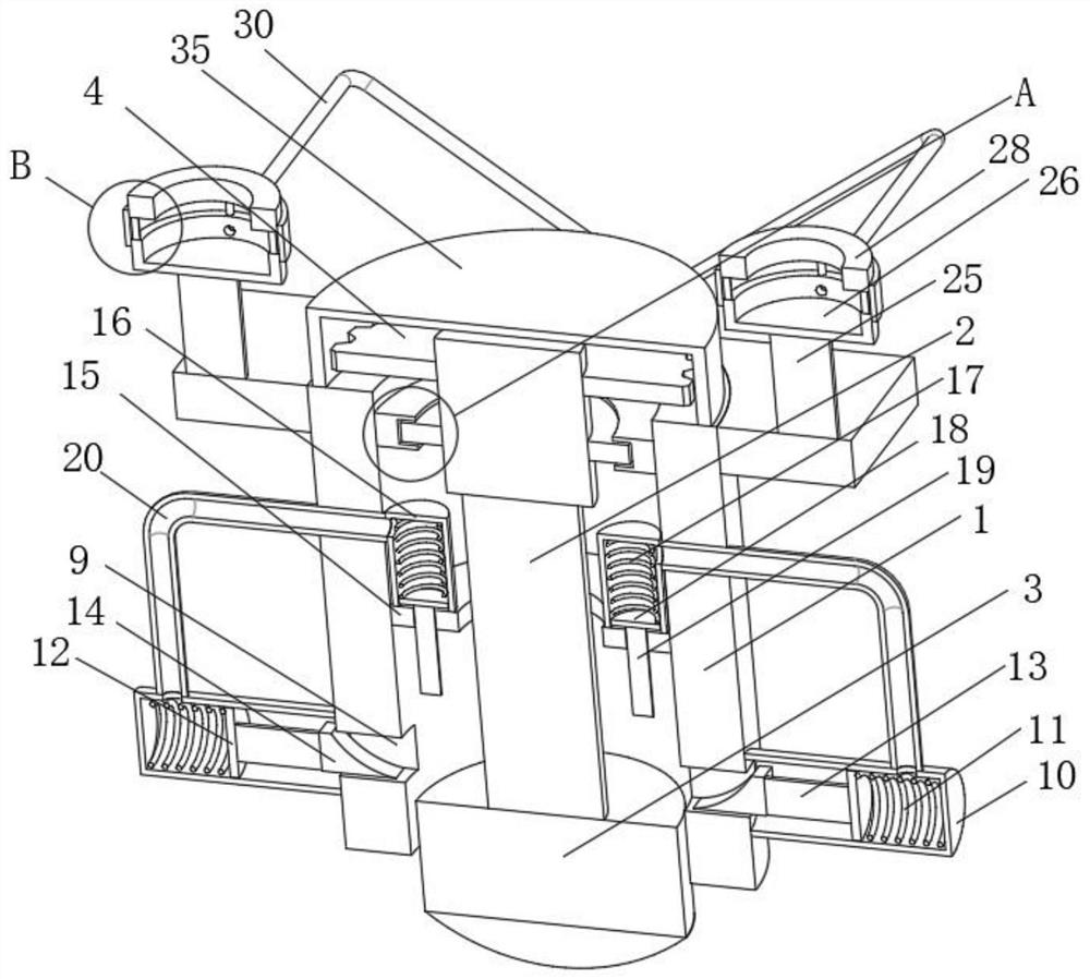
[0039] See Figure 1-8 , A smart home monitoring device, comprising a housing 1, a hydraulic telescopic rod 2 is movably sleeved inside the housing 1, a camera 3 is fixedly installed on the bottom surface of the hydraulic telescopic rod 2, and the outer surface of the hydraulic telescopic rod 2 is fixedly sleeved with a Gear 4, the outer surface of the housing 1 is fixedly connected with a motor base 5, the side of the motor base 5 is fi...


PUM


Abstract

The invention relates to the technical field of monitoring equipment, and discloses a smart home monitoring device which comprises a shell, wherein a hydraulic telescopic rod is movably sleeved with the shell, a camera is fixedly installed on the bottom surface of the hydraulic telescopic rod, and the outer surface of the hydraulic telescopic rod is fixedly sleeved with a first gear. In the sSmarthome monitoring device, as the camera mounted at the bottom end of the hydraulic telescopic rod rotates,; when dust needs to be cleaned up, the hydraulic telescopic rod acts to drive the camera to move upwards when dust needs to be cleaned up,; the movable rod upwards drives the pressing plate to extrude the pressure oil; , and the pressure oil enters the a sealing pipe through the oil pipe; thea bottom surface of the camera rotates to move relative to the cambered cleaning block, so that dust on the surface of the camera is cleaned, the cleaning speed is high, the situation that a worker climbs a ladder to achieve cleaning is avoidedprevented, falling during cleaning is avoidedprevented, the cleaning safety is improved, manual operation is reduced, and the cleaning effect is good.

Description

technical field [0001] The invention relates to the technical field of monitoring equipment, in particular to a smart home monitoring device. Background technique [0002] Surveillance camera is a semiconductor imaging device, which has the advantages of high sensitivity, strong light resistance, small distortion, small size, long life, and vibration resistance. Currently, the image generation in the security system of surveillance cameras mainly comes from CCD cameras. The stored charge is taken out to change the voltage, and it is widely used because of its anti-vibration and impact characteristics. Among them, the monitoring camera can be divided into two types in terms of imaging results. (1) Color camera: suitable for detailed identification of scenes, such as identifying clothing or The color of the scene. Because of the color, the amount of information increases, and the amount of information is generally considered to be 10 times that of black and white cameras. (2)...

Claims


Application Information

Patent Timeline
IPC IPC(8): H04N5/225B08B1/00B08B1/02F16M11/04F16M11/08F16M11/18F16M13/02
CPCB08B1/02B08B1/006B08B1/007F16M13/02F16M11/04F16M11/08F16M11/18H04N23/00
Inventor 沈佩贤
Owner 广州狸园科技有限公司
Why Eureka
Try Eureka