Novel auxiliary device for orthopedic treatment

An auxiliary device and orthopaedic technology, applied in the fields of application, medical science, medical transportation, etc., can solve the problems of secondary injury, speed up recovery, slip, etc., and achieve the effect of easy lifting and fixing, easy rehabilitation and easy use.

Inactive Publication Date: 2020-10-16
刘灿果
View PDF0 Cites 0 Cited by
  • Summary
  • Abstract
  • Description
  • Claims
  • Application Information

AI Technical Summary

Problems solved by technology

[0002] Orthopedics is a diagnostic and treatment subject in medical institutions. It is the general term for trauma and spinal surgery. Deformity, brachial plexus injury and nerve entrapment diagnosis and treatment of professional departments, orthopedic trauma department using a variety of Chinese and Western methods, trauma orthopedics, spinal surgery and joint surgery and other orthopedic surgery, such as: nonunion, bone spine The treatment of inflammation, joint replacement, cervical spondylosis, etc., but in the prior art, orthopedic patients generally lie on the hospital bed to rest in the proc

Method used


Image

  • Novel auxiliary device for orthopedic treatment
  • Novel auxiliary device for orthopedic treatment
  • Novel auxiliary device for orthopedic treatment

Examples


Embodiment 1

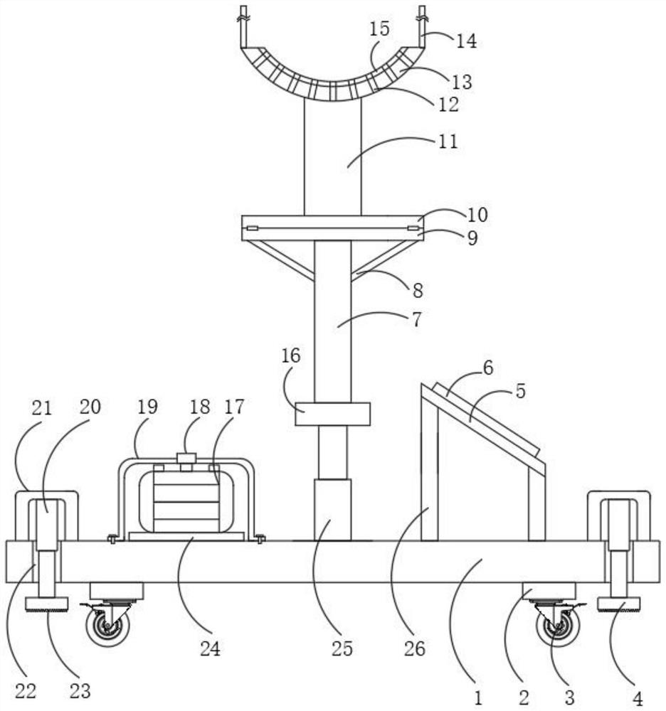
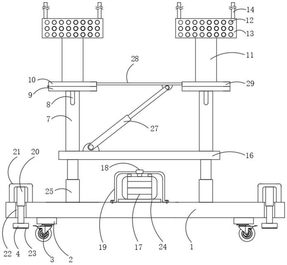
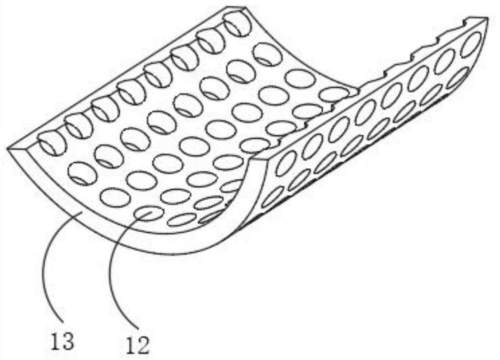
[0023] Embodiment one, with reference to figure 1 , figure 2 , image 3 and Figure 5 : A novel auxiliary device for orthopedic treatment, comprising a base plate 1, the top of the base plate 1 is equipped with first electric telescopic rods 25 close to the edges of the front and rear sides of the two sides, and a length is welded between the tops of the two first electric telescopic rods 25. Plate 16, through the activation of the first electric telescopic rod 25, the height of the long plate 16 can be adjusted. In use, the height of the arc-shaped plate 13 can be adjusted. The top of the long plate 16 is close to the front and rear edges. Both support rods 7 are welded, and the position of the support rods 7 can be welded and fixed by the long plate 16. A fixed plate 9 is welded between the tops of the two support rods 7, and the position of the fixed plate 9 can be fixed by the support rods 7. Fixed by welding, the outer surfaces on both sides of the two support rods 7 ...

Embodiment 2

[0024] Embodiment two, refer to figure 1 and Figure 4: the top of the base plate 1 is provided with through holes 22 along the vertical direction near the four corners, and the through holes 22 are provided so that the third electric telescopic rod 20 can be extended and contracted, which is convenient for use. The top of the base plate 1 is close to each through hole A U-shaped plate 21 is welded between both sides of the hole 22, and the position of the U-shaped plate 21 can be welded and fixed by the bottom plate 1. The third electric telescopic rod 20 is installed at the center of the inner top surface of the U-shaped plate 21, and the second The bottom end of the third electric telescopic rod 20 slides through to the bottom of the through hole 22, and the position of the third electric telescopic rod 20 can be welded and fixed through the U-shaped plate 21. The bottom end of the third electric telescopic rod 20 is fixed with a contact plate 4 , the bottom of the contact...


PUM


Abstract

The invention discloses a novel auxiliary device for orthopedic treatment. The device comprises a bottom plate, wherein first electric telescopic rods are installed at the portions, close to the edgesof the front and rear sides of the two sides, of the top of the bottom plate; a long plate is welded between the tops of the two first electric telescopic rods; and supporting rods are welded to theportions, close to the edges of the front and rear sides, of the top of the long plate. Accordingly, by starting the first electric telescopic rods, the height of the long plate can be adjusted; in use, the height of arc-shaped plates can be adjusted, and use is convenient; meanwhile, by starting second electric telescopic rods, a lifting plate can be lifted as a whole, a turnover plate is turnedover, and one arc-shaped plate is lifted conveniently; in use, the legs of a patient are placed inside the two arc-shaped plates, and by means of hook-and-loop fasteners on the arc-shaped plates, thelegs inside the arc-shaped plates can be fixed; and in use, the legs of the patient are lifted and fixed conveniently, and the patient can use the device for rehabilitation conveniently.

Description

technical field [0001] The invention belongs to the technical field of medical auxiliary devices, in particular to a novel auxiliary device for orthopedic treatment. Background technique [0002] Orthopedics is a diagnostic and treatment subject in medical institutions. It is the general term for trauma and spinal surgery. Deformity, brachial plexus injury and nerve entrapment diagnosis and treatment of professional departments, orthopedic trauma department using a variety of Chinese and Western methods, trauma orthopedics, spinal surgery and joint surgery and other orthopedic surgery, such as: nonunion, bone spine The treatment of inflammation, joint replacement, cervical spondylosis, etc., but in the prior art, orthopedic patients generally lie on the hospital bed to rest in the process of rehabilitation. In order to speed up the recovery of orthopedic patients, the feet of orthopedic patients need to be raised , now it is common to stack multiple pillows together, and th...

Claims


Application Information

Patent Timeline
IPC IPC(8): A61G7/075A61B90/14
CPCA61G7/0755A61G2203/70A61G2210/10A61B90/14
Inventor 刘灿果
Owner 刘灿果
Why Eureka
Try Eureka