Groove milling cutter

A groove milling cutter and cutter head technology, applied in milling cutters, milling machine equipment, manufacturing tools, etc., can solve the problems of poor contact between the coolant and the cutting part of the blade, poor cooling effect of the blade, and affecting the service life of the milling cutter blade. , to achieve the effect of good cooling effect, fast speed and reducing chip sticking to the knife

Active Publication Date: 2020-10-16
台州市英络克工具有限公司
View PDF9 Cites 4 Cited by
  • Summary
  • Abstract
  • Description
  • Claims
  • Application Information

AI Technical Summary

Problems solved by technology

[0004] When the above-mentioned slot milling cutter is used, it is usually necessary to use an external tube to spray coolant on the milling part of the blade. However, during the slotting process, especially when slotting into the hole, the blade extends into the hole and is embedded in the hole during the milling process. In the groove, the coolant sprayed by the external pipe is usually blocked by the groove wall, so that the contact between the coolant and the cutting part of the blade is not good, the cooling effect of the blade is not good, and the service life of the milling cutter blade is affected, which needs to be improved

Method used


Image

  • Groove milling cutter
  • Groove milling cutter
  • Groove milling cutter

Examples


Embodiment

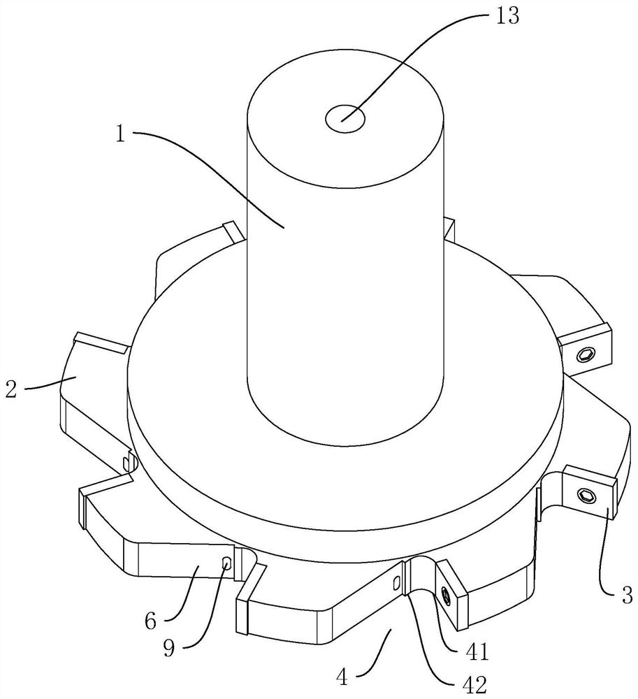
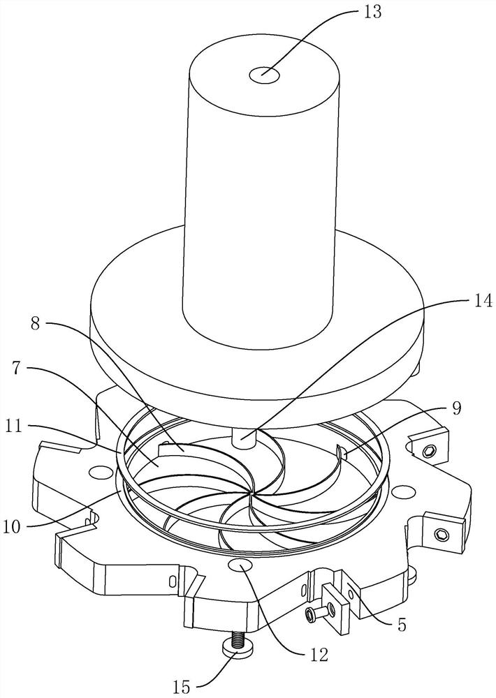
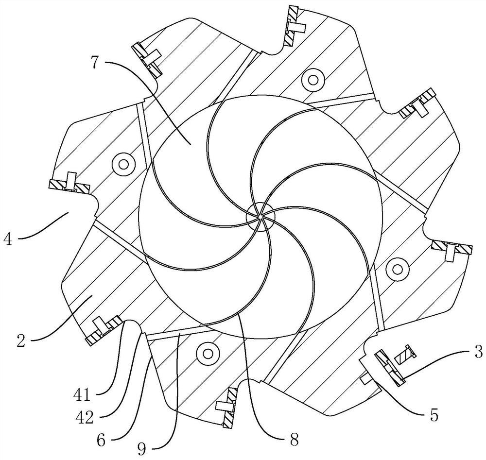
[0036] A slot milling cutter such as figure 1 As shown, it includes a tool handle 1 , a cutter head 2 coaxially fixed at one axial end of the handle 1 , and a blade 3 arranged on the cutter head 2 . The outer wall of the cutter head 2 is provided with at least two knife slots 4 . In this embodiment, there are eight knife slots 4 , and the eight knife slots 4 are evenly distributed along the axis of the cutter head 2 in the circumferential direction.

[0037] Such as figure 1 , figure 2 As shown, each knife slot 4 includes a mounting surface 41 and a material guiding surface 42. In this embodiment, the angle between the mounting surface 41 and the material guiding surface 42 is 70°. The mounting surface 41 of each knife slot 4 is arranged along the radial direction of the cutterhead 2, and the mounting surface 41 is provided with a mounting groove 5, and the mounting groove 5 is arranged through the cutterhead 2 towards an end away from the axis of the cutterhead 2. The num...


PUM


Abstract

The invention discloses a groove milling cutter, and relates to the technical field of milling cutters. The groove milling cutter comprises a cutter handle and a cutter head which is coaxially fixed at one axial end of the cutter handle, at least two blades are uniformly distributed in the circumferential direction of the cutter head, a containing groove is coaxially formed in one end, close to the cutter handle, of the cutter head, the cutter handle covers an opening of the containing groove, a liquid inlet hole which communicates with the containing groove is formed in the cutter handle in the axial direction; the cutter head is further provided with a plurality of liquid discharging holes, the liquid discharging holes correspondingly communicate with the circumferential inner wall of the containing groove, the number of the liquid discharging holes corresponds to the number of the blades, and the liquid discharging holes face the positions, away from the axis of the cutter head, ofthe blades. According to the groove milling cutter, the liquid inlet hole, the containing groove and the liquid discharging holes are formed, so that the blades make more sufficient contact with cooling liquid in the groove milling process of the groove milling cutter, and the cooling effect of the blades is better; and in addition, the cooling liquid sprayed out at a high speed can further carryout impact on cuttings, so that the situation that the cuttings are stuck to the cutter is reduced, and overall use is more stable.

Description

technical field [0001] The invention relates to the technical field of milling cutters, more specifically, it relates to a slot milling cutter. Background technique [0002] A milling cutter is a rotating tool with one or more teeth for milling. Slot milling cutters are mainly used for grooving the workpiece. [0003] For example, the Chinese patent whose patent notification number is CN206605088U discloses a slot milling cutter, which includes a handle, the upper part of the handle is provided with a clamping end, and the lower part of the handle is provided with a cutter head, and the outer wall of the cutter head is Concave along the radial direction to form a plurality of knife slots, all the knife slots are arranged at intervals along the circumferential direction of the cutter head, and each knife slot extends upward or downward along the axial direction of the cutter head to form an opening, and each is placed in the knife slot Each is equipped with a blade, the mai...

Claims


Application Information

Patent Timeline
Patent Type & Authority Applications(China)
IPC IPC(8): B23C5/02B23C5/28
CPCB23C5/02B23C5/28
Inventor 陈立新
Owner 台州市英络克工具有限公司
Why Eureka
Try Eureka