Steel pipe end grooving device

A technology for steel pipes and mounting brackets, applied in positioning devices, clamping devices, clamping, etc., can solve the problems of wasting manpower, easy cutting and skewing, and different slotting depths, and achieve the effect of improving work quality and convenient use

Active Publication Date: 2020-10-16
佛山市南海岐丰钢管有限公司
View PDF7 Cites 7 Cited by
  • Summary
  • Abstract
  • Description
  • Claims
  • Application Information

AI Technical Summary

Problems solved by technology

[0005] In order to overcome the shortcomings of wasting a lot of manpower when grooving the steel pipe, the steel pipe cannot be erected straight, it is easy to cut crookedly, the depth of grooving is different, and the work quality is poor. Steel pipe end grooving device with straight steel pipe and the same groove depth

Method used


Image

  • Steel pipe end grooving device
  • Steel pipe end grooving device
  • Steel pipe end grooving device

Examples


Embodiment 1

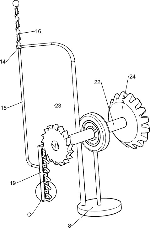
[0020] A steel pipe end grooving device, such as Figure 1-5 As shown, it includes a mounting frame 1, a slotting assembly and a rotating clamping assembly. The upper left side of the mounting frame 1 is provided with a slotting assembly that is slotted by sliding, and the left side of the mounting frame 1 is provided with a slotting assembly that is slotted by sliding. Clamped swivel clamp assembly.

[0021] When grooving the end of the steel pipe, the staff clamps the steel pipe that needs to be grooved by rotating the clamping device, and then the staff grooves the clamped steel pipe through the grooving device. While grooving, the staff rotates Rotate the clamping device to remove the slotted steel pipe for replacement. After the slotting is completed, close the slotting assembly.

[0022] Such as figure 1 As shown, the slotting assembly includes a guide rod 2, a sliding sleeve 3, a first spring 4, a first installation block 5, a handle 6 and an electric cutting knife 7,...

Embodiment 2

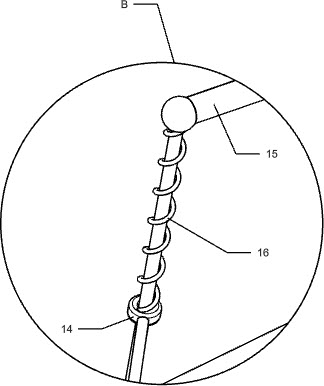
[0027] On the basis of Example 1, such as figure 1 , 3 , 4 and 5, also includes guide sleeve 14, L-shaped slide bar 15, third spring 16, square block 17, push block 18, second mounting block 19, wedge-shaped teeth 20, torsion spring 21, second rotating shaft 22, ratchet 23, the first bevel gear 24 and the second bevel gear 25, the guide sleeve 14 is welded on the top of the installation disk 8, and the inner sliding type of the guide sleeve 14 is provided with an L-shaped slide bar 15, and the L-shaped slide bar 15 and the guide sleeve A third spring 16 is wound around the 14, a square block 17 is welded to the right end of the L-shaped slide bar 15, and a push block 18 is welded on the rear side sliding sleeve 3, and the push block 18 cooperates with the square block 17, and the bottom of the L-shaped slide bar 15 The end is welded with a second mounting block 19, and the second mounting block 19 is evenly spaced and rotated to be provided with six wedge-shaped teeth 20, and...


PUM


Abstract

The invention relates to a grooving device, in particular to a steel pipe end grooving device. According to the technical problem, the steel pipe end grooving device saves manpower, can erect a steelpipe straightly and has the same grooving depth. The steel pipe end grooving device comprises a mounting frame, a grooving assembly and a rotary clamping assembly, wherein the grooving assembly is mounted on the mounting frame and is used for grooving in a sliding manner; and the rotary clamping assembly is mounted on the mounting frame and is used for clamping in a sliding manner. According to the steel pipe end grooving device, the steel pipe can be grooved through the grooving assembly, people can use the steel pipe end grooving device more conveniently, the steel pipe needing to be groovedcan be clamped by the rotary clamping assembly, people can take down the grooved steel pipe to conduct replacement through the rotary clamping assembly while grooving is conducted, and through wedge-shaped teeth, a ratchet wheel, a first bevel gear and a second bevel gear, people do not need to manually rotate a circular ring to replace the steel pipe when grooving the end part of the steel pipeby using equipment.

Description

technical field [0001] The invention relates to a slotting device, in particular to a slotting device at the end of a steel pipe. Background technique [0002] Steel pipes are used to transport fluids and powdery solids, exchange heat, and manufacture mechanical parts and containers. It is also a kind of economical steel. Some of these steel pipes need to be grooved at the ends during use, and are used after being grooved. [0003] At present, when using these steel pipes, people need to slot the ends of the steel pipes. When slotting, people generally place the steel pipes vertically on the ground, hold the steel pipes with one hand, and hold the steel pipes with the other hand. The end of the steel pipe is slotted by the equipment. People waste a lot of manpower by slotting the end of the steel pipe in this way. It is easy to cut crookedly when grooving, which reduces the quality of people's work. When grooving, the depth of grooving also has differences, which affects t...

Claims


Application Information

Patent Timeline
Patent Type & Authority Applications(China)
IPC IPC(8): B23Q3/00B23Q7/00
CPCB23Q3/00B23Q7/00B23Q2703/10
Inventor 王清文
Owner 佛山市南海岐丰钢管有限公司
Why Eureka
Try Eureka