Bar discharging device

A bar material and adjusting device technology, applied in metal processing and other directions, can solve the problems of no steering function, difficult maintenance, complex structure, etc., to achieve the effects of sensitive action, ensuring stability and safety, and high efficiency

Active Publication Date: 2020-10-16
HUBEI UNIV OF ARTS & SCI
View PDF6 Cites 2 Cited by
  • Summary
  • Abstract
  • Description
  • Claims
  • Application Information

AI Technical Summary

Problems solved by technology

[0005] The above-mentioned blanking device for bar processing can realize automatic blanking after processing, but the structure is complicated, difficult to overhaul, and does not have a steering function, and an additional steering drive mechanism is required to realize the blanking steering, which cannot meet the needs of actual production. The position and direction of workpiece blanking are changed to meet the layout requirements of lathes and loading and unloading devices

Method used


Image

  • Bar discharging device
  • Bar discharging device
  • Bar discharging device

Examples


Embodiment 1

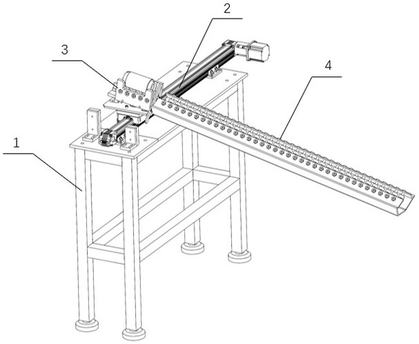
[0047] Such as figure 1 As shown, the embodiment of the present invention provides a bar blanking device, including a workbench 1 , a movement mechanism 2 , an angle adjustment mechanism 3 and a blanking mechanism 4 .

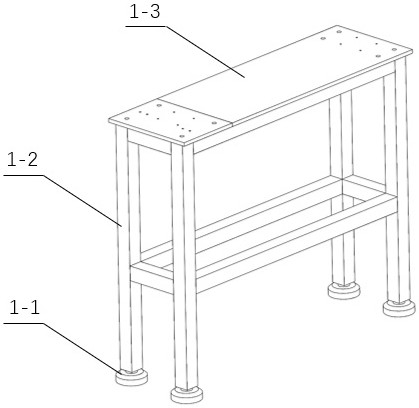
[0048] Such as figure 2As shown, the workbench 1 includes a foot 1-1, a table 1-3 and a table support 1-2 for supporting the table 1-3. One end of the ground foot 1-1 is horizontally placed on the ground, and the other end is connected with the table support 1-2 by bolts. Specifically, the foot 1-1 is an adjustment foot, which may be a plastic foot or a metal foot, and is used to ensure that the device table 1-3 is parallel to the ground. In this embodiment, the table support 1-2 is made by welding square pipes, and ordinary square pipes can be made into the table support 1-2, but it is not limited thereto, any pipe, rod, profile, etc. can be made Table support 1-2, any material can be used as the raw material of table support 1-2, and any fixing method can...

Embodiment 2

[0060] Such as Figure 8 , Figure 9 , Figure 10 As shown, the embodiment of the present invention provides a bar blanking device that can cooperate with the machine tool 5 and the truss manipulator 6 . When blanking, the angle adjustment mechanism 3 is located at the left end of the linear module 2-2, and the truss manipulator 6 picks the bar material processed by the machine tool 5 and places it in the workpiece groove 3-2, and the linear movement of the linear module 2-2 makes the workpiece Slot 3-2 moves to the right (based on attached Figure 7 And attached Figure 9 direction shown).

[0061] During the movement of the workpiece groove 3-2 to the right end, the rotating plate 3-5 touches the moving limit plate 3-9, and the rotating plate 3-5 drives the workpiece groove 3-2 to rotate clockwise around the rotating shaft 3-7 (based on the attached figure 1 directions shown, with Figure 8 And attached Figure 10 is the position after the rotation is completed). Spe...


PUM


Abstract

The invention provides a bar discharging device. The bar discharging device comprises a moving mechanism and an angle adjusting mechanism. The angle adjusting mechanism can be driven by the moving mechanism to move between a feeding region and a discharging region back and forth. The angle adjusting mechanism comprises a workpiece groove, a rotary plate and an adjusting device. A discharge port isformed in one end of the workpiece groove, a workpiece groove bottom plate is arranged at the bottom of the workpiece groove, one side of the workpiece groove bottom plate is hinged to the rotary plate, a rotary shaft penetrates through the middle of the rotary plate, and the rotary plate drives the workpiece groove to rotate around the rotary shaft. The adjusting device comprises a horizontal rotation adjusting device and a vertical angle adjusting device. The horizontal rotation adjusting device comprises a movable limiting plate arranged in the discharging region and can limit the horizontal rotation angle of the workpiece groove. The vertical angle adjusting device comprises a vertical adjusting bolt simultaneously connected with the workpiece groove bottom plate and the rotary plateand used for adjusting the included angle between the workpiece groove bottom plate and the rotary plate to enable bars to slip out from the discharge port through the gravity of the bars. Multi-angledischarging can be achieved, and the requirements that the discharging positions of the workpieces need to be changed in actual production are met.

Description

technical field [0001] The invention relates to a bar blanking device, which belongs to the technical field of bar processing. Background technique [0002] Bar stock refers to a round or polygonal stick-shaped material with a certain length for plates and other profiles, which are generally processed by machine tools. [0003] In the prior art, two methods are generally adopted for the blanking of bar workpieces. The first method is to use manual blanking. This method can meet the requirements of the accuracy of the blanking workpiece, but it is time-consuming and laborious. Certain risk of accident. According to statistics, in the process of workpiece processing, its supply, loading, unloading and handling processes account for about two-thirds of the total working hours, and the cost accounts for about one-third of the total cost, and most of the accidents are occur in these processes. [0004] The other is to use a device for cutting. For example, the Chinese patent ...

Claims


Application Information

Patent Timeline
Patent Type & Authority Applications(China)
IPC IPC(8): B23Q7/00B23Q7/04B23Q7/08
CPCB23Q7/00B23Q7/008B23Q7/04B23Q7/08
Inventor 秦涛魏超邱金星温景阳杨沫王乙坤李波
Owner HUBEI UNIV OF ARTS & SCI
Why Eureka
Try Eureka