Colored glass manufacturing process

A production process, a technology for stained glass, applied in the direction of manufacturing tools, processes for producing decorative surface effects, decorative arts, etc., and can solve problems such as extrusion and cracking

Inactive Publication Date: 2020-10-16
李晓洁
View PDF0 Cites 0 Cited by
  • Summary
  • Abstract
  • Description
  • Claims
  • Application Information

AI Technical Summary

Problems solved by technology

[0006] In order to make up for the deficiencies of the prior art, to solve the problem that when the glass knife cuts along the scratch for many times, when the glass blade squeezes the glass debris in the scratch, the glass debris will squeeze and break the edge of the scratch, the present invention Proposed a process for making stained glass

Method used


Image

  • Colored glass manufacturing process
  • Colored glass manufacturing process
  • Colored glass manufacturing process

Examples


Embodiment approach

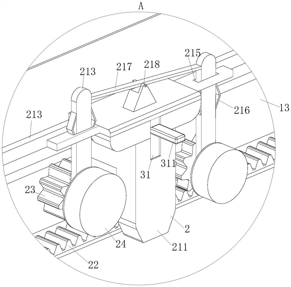
[0036] As a specific embodiment of the present invention, the lower end surface of the cutting seat 21 has a first cavity 3, and the front end surface of the cutting seat 21 has a second groove 31, and the second groove 31 communicates with the first cavity 3, and the second groove 31 communicates with the first cavity 3. Slot 31 is provided with driving lever 311, and driving lever 311 is connected in No. 2 groove 31 by No. 1 spring 312, and the lower end of driving lever 311 is hinged cutting knife 212 in No. 1 cavity 3; The cooperation between the rod 311 and the No. 1 spring 312 realizes the protection of the cutting knife 212; the cutting knife 212 is a cutting part of the cutting device, and the cutting knife 212 needs to be protected to prevent the cutting knife 212 from colliding with external objects, resulting in cutting The blade of knife 212 is damaged, for this reason, by hiding cutting knife 212 in the No. 1 cavity 3, when cutting knife 212 is in use, by pressing ...

specific Embodiment approach

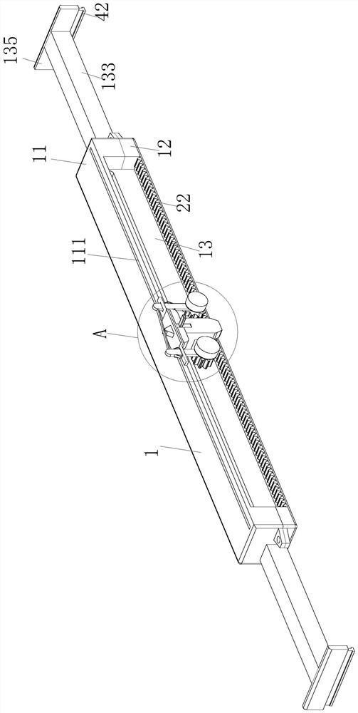
[0037] As a specific embodiment of the present invention, a No. 3 slot 132 is set behind the No. 1 slot 13, and the No. 3 slot 132 runs through both ends of the sliding board 1. There are symmetrical sliding rods 133 arranged in the No. 3 slot 132, and The opposite surfaces of the two sliding rods 133 are connected together by the No. 2 spring 134, and the ends of the two sliding rods 133 are fixed to the baffle plate 135 respectively; when the cutting device is not in use, the two sliding rods 133 retract into the third slot 132 ; Through the cooperation between No. 3 slot 132, sliding rod 133 and baffle plate 135, the cutting knife 212 can cut the glass stably; because the glass surface is smooth, when the cutting device is placed on the glass surface, press the driving lever 311 firmly , the cutting device will slide between the glass, for this reason the cutting device is fixed on the glass plate surface through the sliding rod 133 and the baffle plate 135, and the baffle p...


PUM


Abstract

The invention belongs to the technical field of glass, and particularly relates to a colored glass manufacturing process. A cutting device used in the process comprises a glide plate; the glide platecomprises an upper shell and a lower shell; two ends of the upper shell and the lower shell are connected through a bolt; a No.1 slot is formed between the upper shell and the lower shell; a cutting unit is arranged in the No.1 slot, and comprises a cutting base, a rack, gears and hairbrushes; a T-shaped rod is arranged at the rear end of the cutting base and is embedded into a T-shaped groove formed in the No.1 slot; a cutter is arranged at the lower end of the cutting base; connecting plates are arranged on two sides of the cutting base; a No.1 rod is hinged to the lower end of each connecting plate; one hairbrush is fixedly connected to the front end of each No.1 rod; one gear is fixedly connected to the rear end of each No.1 rod and meshes with the rack placed on the lower bottom faceof the No.1 slot; and through the cutting unit, glass can be cut, and glass slags in a glass cutting seam can be cleaned.

Description

technical field [0001] The invention belongs to the technical field of glass, in particular to a manufacturing process of colored glass. Background technique [0002] Visual color decoration is used in home decoration stained glass decoration, mainly for windows, curtain walls, murals, partitions, as small as lampshades, light boxes, and handicrafts, forming a strong color of oriental art. The thread passes through the stained glass and enters the room, where it becomes very colorful and produces some wonderful effects. Light and shadow show the powerful charm of stained glass. [0003] After the colored glass is produced, it is cut into various shapes by a glass knife according to the needs of users. When the glass knife cuts the glass with lines, the glass knife cuts scratches on the glass surface, and the scratches remain There are glass debris, when the glass knife cuts along the scratch again, the blade of the glass knife squeezes the glass debris, so that the glass de...

Claims


Application Information

Patent Timeline
Patent Type & Authority Applications(China)
IPC IPC(8): B28D1/24B28D7/00B28D7/02B28D7/04B44C1/17
CPCB28D1/24B28D7/00B28D7/02B28D7/04B44C1/1712
Inventor 李晓洁程明
Owner 李晓洁
Why Eureka
Try Eureka