Diving equipment with adjustable buoyancy

A diving equipment and buoyancy technology, applied in underwater operation equipment, transportation and packaging, ships, etc., can solve the problems of increasing breathable gas capacity, increasing diving time, reducing buoyancy to achieve diving, etc., to shorten the time Waiting time, extending the diving time, increasing the effect of storage

Active Publication Date: 2021-11-05
ANHUI KANGYU HYDROPOWER MACHINERY COMPLETE EQUIP CO LTD
View PDF6 Cites 0 Cited by
  • Summary
  • Abstract
  • Description
  • Claims
  • Application Information

AI Technical Summary

Problems solved by technology

[0003] Chinese invention CN106477011A discloses a buoyancy adjustment and pressure compensation system and method for submersibles, including a shell, which is filled with a certain pressure of gas, and more than two elastic airbags are installed on the shell, and the elastic airbags are filled with Gas at a certain pressure, and through the perforated protective shell covering it, is in contact with the inside and outside of the housing. The pressure of the gas inflated in each elastic airbag is different, and the gas pressure in the housing is lower than that in the elastic airbag. The gas pressure; the shell is equipped with an elastic water bag, a two-way seawater hydraulic pump and a seawater solenoid valve. When diving, the control system controls the seawater solenoid valve to energize and connect the one-way waterway from the external water environment to the elastic water bag. When the gas pressure is greater than or equal to the pressure of the external water environment, the control system controls the motor to rotate and drive the two-way seawater hydraulic pump to press the water in the external water environment into the elastic water bag. The volume of the shell remains unchanged and the mass increases to achieve diving, but the structure is complicated and the cost is high. The function is single and can only reduce the buoyancy to achieve the purpose of diving. The volume occupied by the gas inside the device cannot be converted into breathable gas storage after the reduction, and the capacity of breathable gas cannot be increased while reducing the buoyancy to achieve the dive. , increasing the dive time

Method used


Image

  • Diving equipment with adjustable buoyancy
  • Diving equipment with adjustable buoyancy
  • Diving equipment with adjustable buoyancy

Examples


Embodiment 1

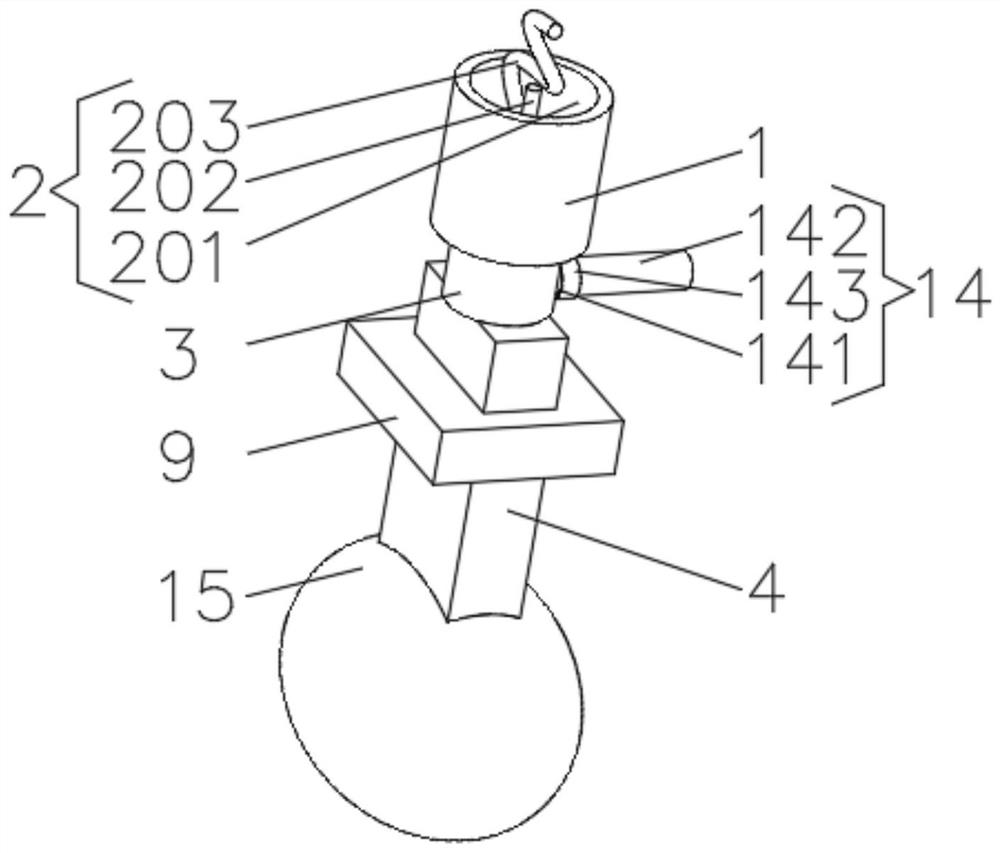
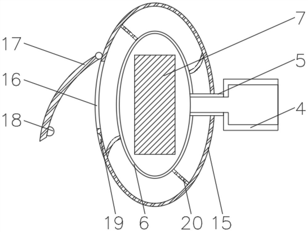
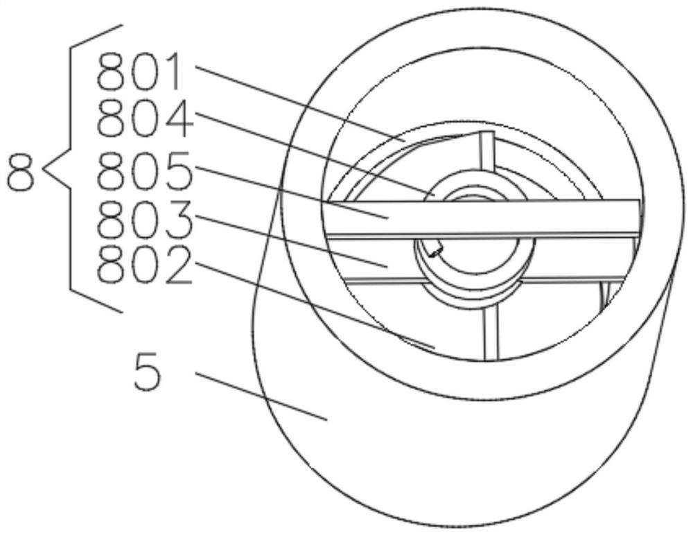
[0028] see Figure 1-6 , the present invention provides a technical solution: a diving equipment with adjustable buoyancy, including a fixed block 1, a binding device 2 is installed on the top of the fixed block 1, an air storage pipe 3 is fixedly connected to the bottom of the fixed block 1, and the air storage pipe 3 The bottom of the hose 4 is connected with the hose 4, and the end of the hose 4 away from the gas storage pipe 3 is connected with the floating ball 6 through the control pipe 5. The inside of the floating ball 6 is filled with a weight block 7, and the inside of the control pipe 5 is equipped with an exhaust device 8. The outer side of the flexible pipe 4 is provided with an air extraction block 9, and one side of the inner wall of the air extraction block 9 is provided with a driving groove 10, and a gear 11 is rotationally connected between the two sides of the inner wall of the driving groove 10, and one side of the flexible pipe 4 is provided with a The ge...

Embodiment 2

[0034] see Figure 1-6 , the present invention provides a technical solution: on the basis of Embodiment 1, a suction pipe 14 is connected to one side of the gas storage pipe 3, and the suction pipe 14 includes an inner rod 141, which is fixedly connected to the gas storage pipe 3, and the inner rod 141 is fixedly connected to the gas storage pipe 3. The rod 141 is an externally threaded rod, the outer side of the inner rod 141 is provided with a suction hose 142, the suction hose 142 communicates with the gas storage pipe 3, and the outer side of the suction hose 142 is provided with a fitting suitable for the inner rod 141. Internally threaded pipe 143 .

[0035] When in use, turn the internally threaded pipe 143 until the internally threaded pipe 143 is fixed on the inner rod 141, the connection between the suction hose 142 and the gas storage pipe 3 is blocked by the internally threaded pipe 143 and the internal rod 141 and cannot be ventilated. It is found that the inter...

Embodiment 3

[0037] see Figure 1-6 , the present invention provides a technical solution: on the basis of the second embodiment, the outer side of the floating ball 6 is covered with a protective sleeve 15, and the end of the control tube 5 away from the floating ball 6 passes through the protective sleeve 15 and extends to the outside of the protective sleeve 15 , one side of the protective cover 15 is provided with an exhaust port 16, and the outer side of the protective cover 15 is rotatably connected with a sealing block 17 near the position of the exhaust port 16, and a buckle 18 is installed on one side of the sealing block 17, and the outer side of the protective cover 15 A card slot 19 matching the buckle 18 is provided.

[0038] The outer side of the floating ball 6 is evenly equipped with an elastic rope 20 , and the end of the elastic rope 20 away from the floating ball 6 is fixedly connected with the protective cover 15 .

[0039] During use, fill gas into the protective cove...


PUM


Abstract

The invention discloses a diving equipment with adjustable buoyancy, which relates to the technical field of diving equipment. The bottom of the air pipe is connected with a hose, the end of the hose away from the air storage pipe is connected with a floating ball through a control pipe, the inside of the floating ball is filled with a weight block, and an exhaust device is installed in the inside of the control pipe. The outer side of the hose is sleeved with an air extraction block, a driving groove is opened on one side of the inner wall of the air extraction block, a gear is rotatably connected between the two sides of the inner wall of the driving groove, and one side of the hose is provided with a gear groove. The buoyancy-adjustable diving equipment can simplify the structure of the buoyancy adjustment device of the diving equipment, reduce the cost of the diving equipment, increase the function of the buoyancy adjustment device, and increase the storage of breathable gas while reducing the buoyancy of the equipment to achieve diving. Increase dive time.

Description

technical field [0001] The invention relates to the technical field of diving equipment, in particular to diving equipment with adjustable buoyancy. Background technique [0002] The original intention of diving is to carry out underwater surveys, salvage, repairs and underwater engineering operations, with or without carrying professional tools to enter the activities below the surface of the water, and then diving has gradually developed into an activity that focuses on underwater activities. Content, so as to achieve the purpose of physical exercise, leisure and entertainment leisure sports, widely loved by the public. In order to achieve a deeper dive, it is usually necessary to carry tools to increase the gravity of the diver. [0003] Chinese invention CN106477011A discloses a buoyancy adjustment and pressure compensation system and method for submersibles, including a shell, which is filled with a certain pressure of gas, and more than two elastic airbags are install...

Claims


Application Information

Patent Timeline
Patent Type & Authority Patents(China)
IPC IPC(8): B63C11/02
CPCB63C11/02
Inventor 王佩贵
Owner ANHUI KANGYU HYDROPOWER MACHINERY COMPLETE EQUIP CO LTD
Why Eureka
Try Eureka