Diving equipment with adjustable buoyancy
A diving equipment and buoyancy technology, applied in underwater operation equipment, transportation and packaging, ships, etc., can solve the problems of increasing breathable gas capacity, increasing diving time, reducing buoyancy to achieve diving, etc., to shorten the time Waiting time, extending the diving time, increasing the effect of storage
- Summary
- Abstract
- Description
- Claims
- Application Information
AI Technical Summary
Problems solved by technology
Method used
Image
Examples
Embodiment 1
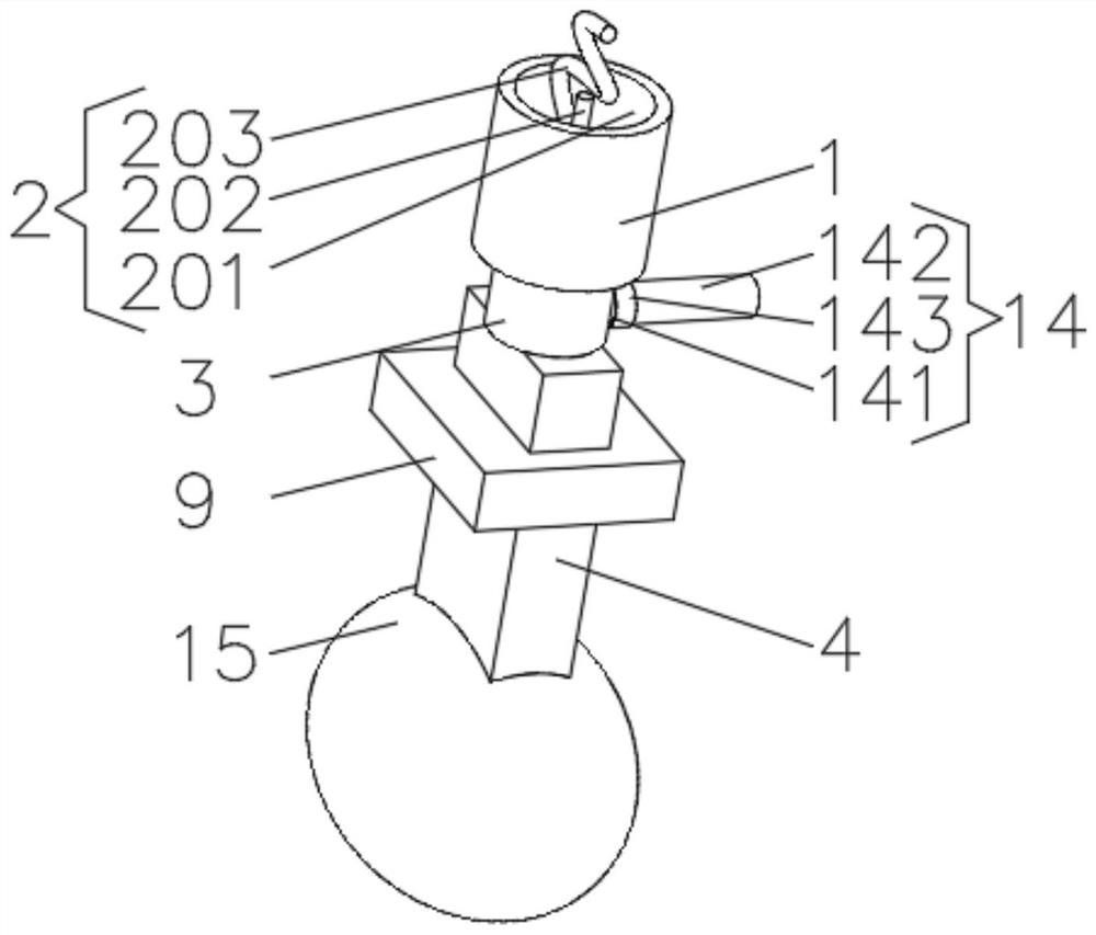
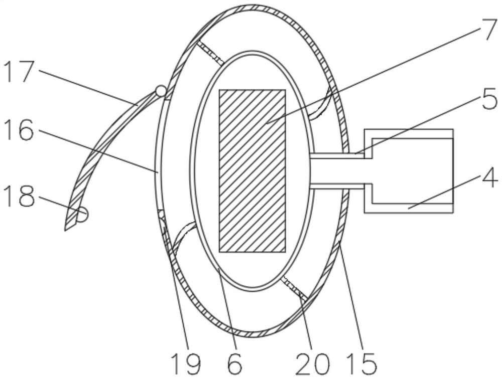
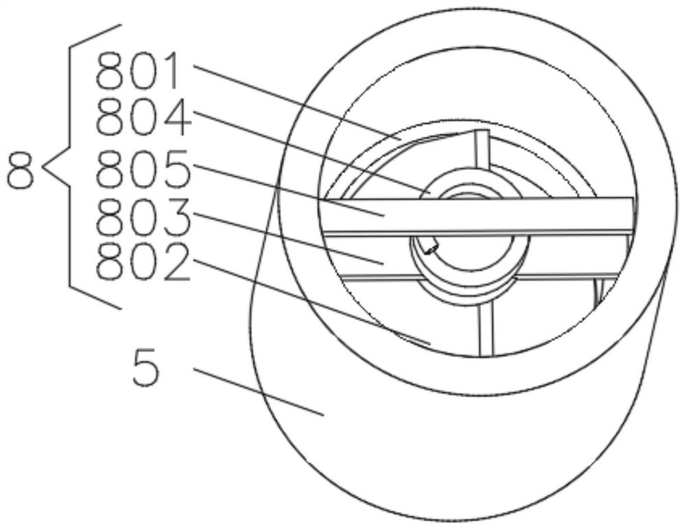
[0028] see Figure 1-6 , the present invention provides a technical solution: a diving equipment with adjustable buoyancy, including a fixed block 1, a binding device 2 is installed on the top of the fixed block 1, an air storage pipe 3 is fixedly connected to the bottom of the fixed block 1, and the air storage pipe 3 The bottom of the hose 4 is connected with the hose 4, and the end of the hose 4 away from the gas storage pipe 3 is connected with the floating ball 6 through the control pipe 5. The inside of the floating ball 6 is filled with a weight block 7, and the inside of the control pipe 5 is equipped with an exhaust device 8. The outer side of the flexible pipe 4 is provided with an air extraction block 9, and one side of the inner wall of the air extraction block 9 is provided with a driving groove 10, and a gear 11 is rotationally connected between the two sides of the inner wall of the driving groove 10, and one side of the flexible pipe 4 is provided with a The ge...
Embodiment 2
[0034] see Figure 1-6 , the present invention provides a technical solution: on the basis of Embodiment 1, a suction pipe 14 is connected to one side of the gas storage pipe 3, and the suction pipe 14 includes an inner rod 141, which is fixedly connected to the gas storage pipe 3, and the inner rod 141 is fixedly connected to the gas storage pipe 3. The rod 141 is an externally threaded rod, the outer side of the inner rod 141 is provided with a suction hose 142, the suction hose 142 communicates with the gas storage pipe 3, and the outer side of the suction hose 142 is provided with a fitting suitable for the inner rod 141. Internally threaded pipe 143 .
[0035] When in use, turn the internally threaded pipe 143 until the internally threaded pipe 143 is fixed on the inner rod 141, the connection between the suction hose 142 and the gas storage pipe 3 is blocked by the internally threaded pipe 143 and the internal rod 141 and cannot be ventilated. It is found that the inter...
Embodiment 3
[0037] see Figure 1-6 , the present invention provides a technical solution: on the basis of the second embodiment, the outer side of the floating ball 6 is covered with a protective sleeve 15, and the end of the control tube 5 away from the floating ball 6 passes through the protective sleeve 15 and extends to the outside of the protective sleeve 15 , one side of the protective cover 15 is provided with an exhaust port 16, and the outer side of the protective cover 15 is rotatably connected with a sealing block 17 near the position of the exhaust port 16, and a buckle 18 is installed on one side of the sealing block 17, and the outer side of the protective cover 15 A card slot 19 matching the buckle 18 is provided.
[0038] The outer side of the floating ball 6 is evenly equipped with an elastic rope 20 , and the end of the elastic rope 20 away from the floating ball 6 is fixedly connected with the protective cover 15 .
[0039] During use, fill gas into the protective cove...
PUM
 Abstract
Description
Claims
Application Information
 - R&D
- Intellectual Property
- Life Sciences
- Materials
- Tech Scout
- Unparalleled Data Quality
- Higher Quality Content
- 60% Fewer Hallucinations
Browse by: Latest US Patents, China's latest patents, Technical Efficacy Thesaurus, Application Domain, Technology Topic, Popular Technical Reports.
© 2025 PatSnap. All rights reserved.Legal|Privacy policy|Modern Slavery Act Transparency Statement|Sitemap|About US| Contact US: help@patsnap.com


