Silo

A silo and material technology, applied in the field of gear processing equipment, can solve the problems of large floor area, limited number of workpieces, and affecting production efficiency, and achieve the effects of small floor area, high production efficiency, and strong practicability

Pending Publication Date: 2020-10-16
HUNAN ZDCY (ZHONGDA CHUANG YUAN) CNC EQUIP CO LTD
View PDF1 Cites 2 Cited by
  • Summary
  • Abstract
  • Description
  • Claims
  • Application Information

AI Technical Summary

Problems solved by technology

This production method occupies a large area, and because the number of workpieces that can be placed on the material tray is limited, workers need to frequently replace the material trays in the area to be processed and the material trays in the processed area, which affects production efficiency

Method used


Image

  • Silo
  • Silo
  • Silo

Examples


Embodiment Construction

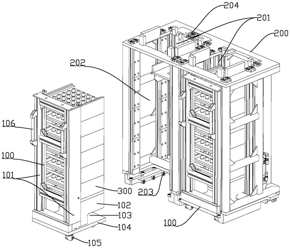
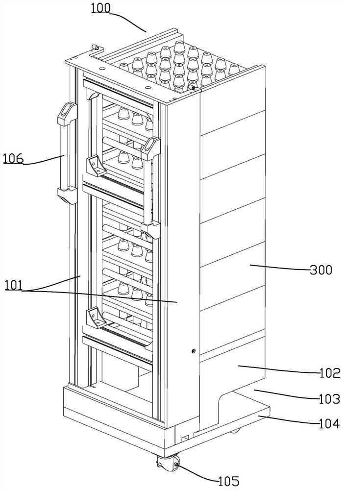
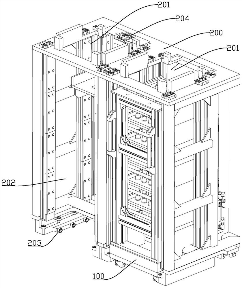
[0022] Embodiments of the present invention are described in detail below, examples of which are shown in the drawings, wherein the same or similar reference numerals designate the same or similar elements or elements having the same or similar functions throughout. The embodiments described below by referring to the figures are exemplary only for explaining the present invention and should not be construed as limiting the present invention.

[0023] In describing the present invention, it should be understood that the terms "center", "longitudinal", "transverse", "length", "width", "thickness", "upper", "lower", "front", " Rear", "Left", "Right", "Vertical", "Horizontal", "Top", "Bottom", "Inner", "Outer", "Axial", "Radial", "Circumferential" The orientation or positional relationship indicated by etc. is based on the orientation or positional relationship shown in the drawings, and is only for the convenience of describing the present invention and simplifying the descriptio...


PUM


Abstract

The invention discloses a silo which is provided with at least two pick-and-place positions. A parking area is arranged under each of the pick-and-place positions, and a cart capable of being pushed out is arranged in each parking area. A plurality of material trays are stacked on each cart, the material trays are used to place processed workpieces and/or workpieces to be processed, lifting mechanisms are arranged in the parking areas, and the lifting mechanisms are used to lift the material trays to the pick-and-place positions. The silo can use one pick-and-place position for loading and onepick-and-place position for unloading, the workpieces to be processed and the processed workpieces are integrated into one silo, the floor space is small, the requirement on area of a plant can be reduced, the production cost is reduced, a plurality of material trays are stacked on each cart, so that more workpieces can be placed, only when all the workpieces on the material trays on the cart areprocessed, replacing is needed, so that the production efficiency is greatly improved, and the practicability is high.

Description

technical field [0001] The invention relates to gear processing equipment, in particular to a material bin. Background technique [0002] During the processing of most mechanical equipment equipped with automatic loading and unloading mechanisms, workpieces (such as spiral bevel gears) are stored on material trays for transfer and transmission, such as Figure 5 The structure shown is a circular workpiece transfer transmission mechanism. During the production process, it is necessary to put the workpiece to be processed into the transmission mechanism and take out the processed workpiece through the manipulator. Therefore, it is necessary to set up an area to be processed next to the processing equipment to place the workpiece to be processed. Set the processed area to place processed workpieces. This production method occupies a large area, and because the number of workpieces that can be placed on the material tray is limited, workers need to frequently replace the materia...

Claims


Application Information

Patent Timeline
Patent Type & Authority Applications(China)
IPC IPC(8): B65G1/04B62B3/00B62B3/04
CPCB65G1/0492B65G1/04B62B3/04B62B3/00
Inventor 张春晖
Owner HUNAN ZDCY (ZHONGDA CHUANG YUAN) CNC EQUIP CO LTD
Why Eureka
Try Eureka