
Multistage separating micro-fluidic chip for cells

A microfluidic chip, cell technology, applied in laboratory containers, enzymology/microbiology devices, methods of supporting/immobilizing microorganisms, etc. The problem of low recovery purity, etc., achieves the effects of easy integration, miniaturization, high-purity sorting, and simple operation.

Active Publication Date: 2020-10-16
SOUTHEAST UNIV
View PDF4 Cites 4 Cited by
  • Summary
  • Abstract
  • Description
  • Claims
  • Application Information

AI Technical Summary

Problems solved by technology

At present, the sorting technology is mainly divided into active and passive. The active cell sorting technology needs to use external electric, sound, light, magnetic and other physical fields to exert force on the cells to achieve cell sorting. The sorting accuracy is high, but its The cost is high, and it is difficult to achieve high-throughput sorting; passive cell sorting refers to not relying on external physical fields, but only relying on the physical structure of the microfluidic chip itself or the fluid dynamics generated by the interaction between cells in the flow channel, so as to achieve cell separation. The sorting method of position differentiation in the flow channel is mainly based on physical properties such as particle density, shape, and deformability. Passive sorting meets the requirements of high-throughput sorting, and has a simple structure and low cost. Low selection accuracy and low recovery purity

Method used


Image

  • Multistage separating micro-fluidic chip for cells
  • Multistage separating micro-fluidic chip for cells
  • Multistage separating micro-fluidic chip for cells

Examples


Embodiment Construction

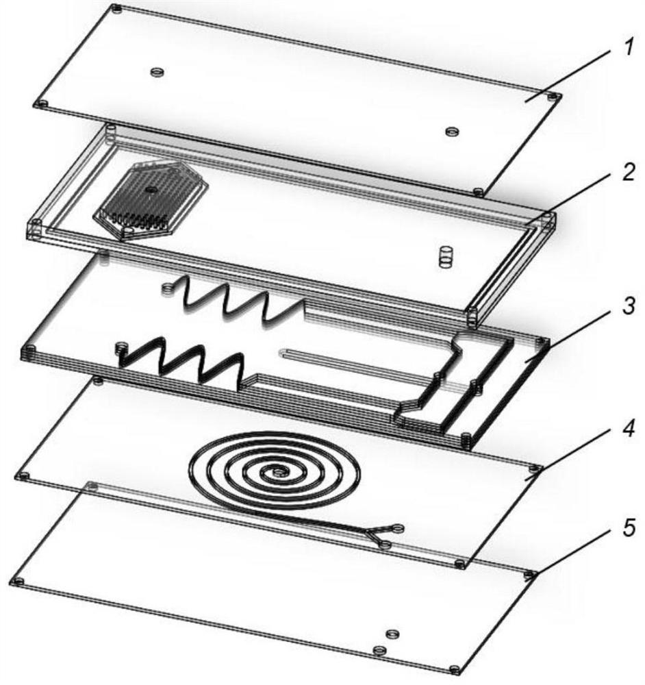
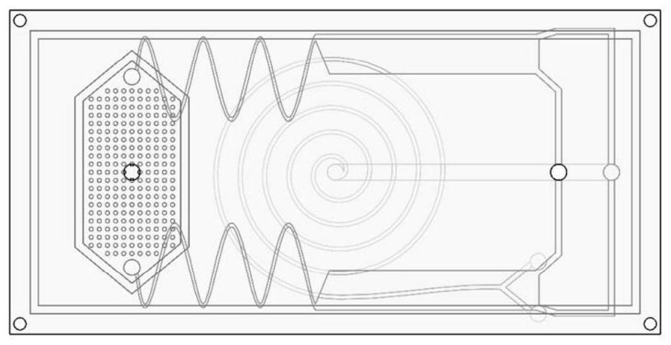
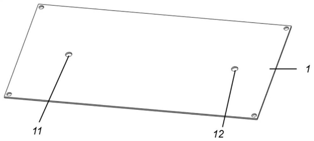
[0018] Such as figure 1 , figure 2 As shown, the multi-stage sorting microfluidic chip for cells is composed of an upper cover plate 1, a filter layer 2, a magnetic separation layer 3, a spiral separation layer 4 and a lower cover plate 5, as shown in image 3 , Figure 5 As shown, the upper cover plate 1 is provided with a first sample liquid inlet 11 and a first magnetic bead channel 12, and the filter layer 2 is provided with a second sample liquid inlet 21 communicating with the first sample liquid inlet 11, a filter cavity Chamber 22, the second magnetic bead channel 25 communicated with the first magnetic bead channel and the magnetic bead outlet 35, and the sample liquid outlet 24 communicated with the third sample liquid inlet 31, the filter chamber 22 is provided with a circular cross section Filter microcolumn 23, such as Image 6 as shown, Figure 7 As shown, the magnetic separation module 3 is composed of three separation layers and one flow guide layer 37. Th...


PUM


Abstract

The invention discloses a multistage separating micro-fluidic chip for cells. The multistage sorting micro-fluidic chip consists of an upper cover plate, a filter layer, a magnetic separating layer, aspiral separating layer, and a lower cover plate which are overlapped, wherein the magnetic separating layer consists of a separating layer and a diversion layer; third sample liquid inlets, a focussine flow channel, an abrupt expansion structure and a magnetic separating flow channel are arranged on the separating layer; a magnetic bead outlet and a first cell outlet are formed in the magneticseparating flow channel; a diversion layer inlet, a diversion layer flow channel and a diversion layer outlet are formed in the diversion layer; a fourth sample liquid inlet, a spiral flow channel, asecond cell outlet and a third cell outlet are formed in the spiral separating layer; and the diversion layer outlet communicates with the fourth sample liquid inlet. The chip integrates magnetic andinertia spiral separating two-stage flow channels, and sufficiently adopts high-flux advantages of inertia spiral separating and high-precision advantages of magnetic separating, so that high-flux high-purity separating on different cells can be realized, the cost is low, the operation is simple, and integrated miniaturization is easy to realize.

Description

technical field [0001] The invention relates to a microfluidic chip, in particular to a microfluidic chip for multistage sorting of cells. Background technique [0002] Microfluidic technology precisely manipulates microliter and milliliter samples through micron-scale flow channels. Thanks to its characteristic size that just matches the cell size, these microfluidic devices have the inherent advantages of low sample consumption and high control accuracy. The potential for sorting applications is huge. At present, the sorting technology is mainly divided into active and passive. The active cell sorting technology needs to use external electric, sound, light, magnetic and other physical fields to exert force on the cells to achieve cell sorting. The sorting accuracy is high, but its The cost is high, and it is difficult to achieve high-throughput sorting; passive cell sorting refers to not relying on external physical fields, but only relying on the physical structure of th...

Claims


Application Information

Patent Timeline
IPC IPC(8): C12M1/42C12M1/12C12M1/00B01L3/00
CPCC12M47/04B01L3/5027B01L3/502753
Inventor 倪中华项楠周宇杰韩煜
Owner SOUTHEAST UNIV
Learn More