
Cooling equipment for special copper bar smelting forming

A technology of cooling equipment and copper rods, which is applied to mechanical equipment, parts of pumping devices for elastic fluids, and lubrication of engines, etc., which can solve the problem of easy blockage of the air outlet on the surface of the dustproof screen frame, reduction of the rotation efficiency of the rotating shaft, Problems such as increased friction of the rotating shaft, etc., to facilitate cleaning work, improve cooling effect, and improve stability

Active Publication Date: 2020-10-16
江西云泰铜业有限公司
View PDF11 Cites 1 Cited by
  • Summary
  • Abstract
  • Description
  • Claims
  • Application Information

AI Technical Summary

Problems solved by technology

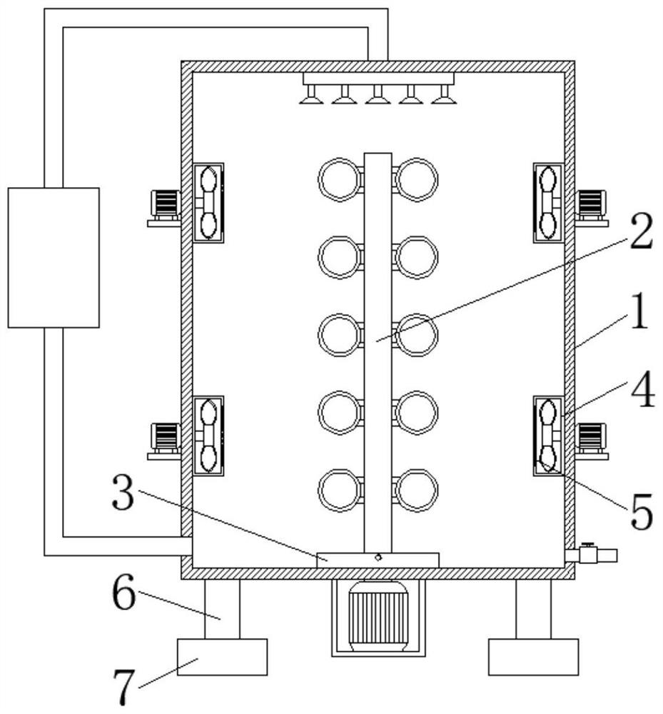
[0003] However, the existing cooling equipment for special copper rod smelting and forming, when the equipment is used for a long time, the friction between the rotating shaft and the rotating seat becomes larger, reducing the rotation efficiency of the rotating shaft. There are too many dust and other impurities on the surface of the dust screen frame, which can easily block the air outlet on the surface of the dust screen frame, and the vibration generated when the equipment cannot buffer the operation, which is likely to cause damage to the components in the equipment. Therefore, we propose a cooling equipment for special copper rod smelting and forming

Method used


Image

  • Cooling equipment for special copper bar smelting forming
  • Cooling equipment for special copper bar smelting forming
  • Cooling equipment for special copper bar smelting forming

Examples


Embodiment Construction

[0026] The following will clearly and completely describe the technical solutions in the embodiments of the present invention with reference to the accompanying drawings in the embodiments of the present invention. Obviously, the described embodiments are only some, not all, embodiments of the present invention. Based on the embodiments of the present invention, all other embodiments obtained by persons of ordinary skill in the art without making creative efforts belong to the protection scope of the present invention.

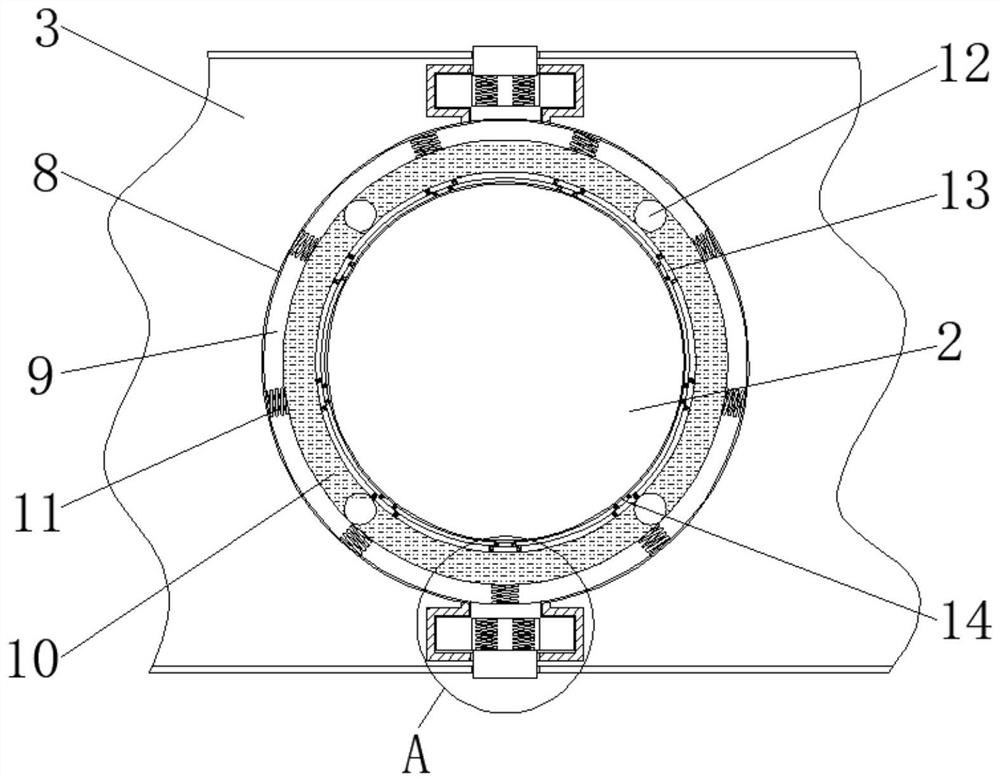
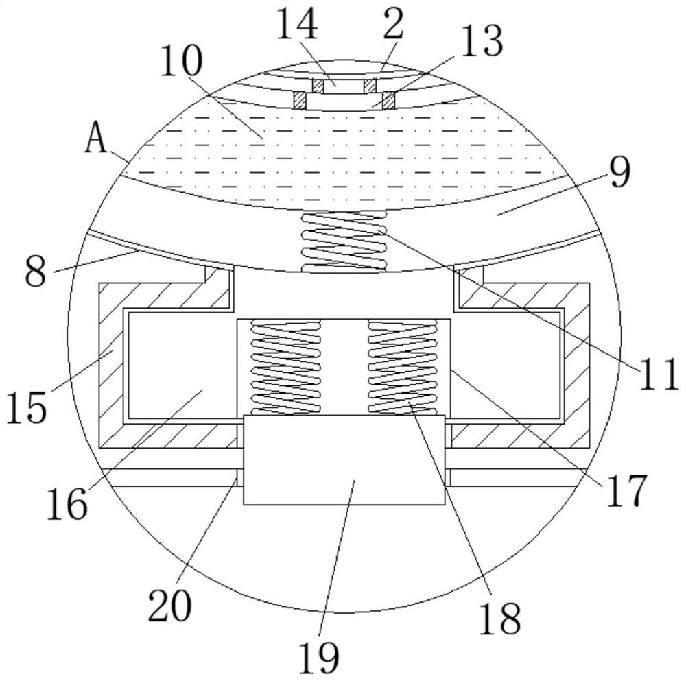
[0027] see Figure 1-6 , the present invention provides a technical solution: a cooling device for special copper rod smelting and forming, including a device body 1, a lubricating mechanism, a cleaning mechanism, and a shock absorbing mechanism. The inside of the device body 1 is provided with a rotating shaft 2. The surface is provided with a rotating base 3, the rotating shaft 2 runs through the rotating base 3 and is connected to the equipment body 1, the ...


PUM


Abstract

The invention discloses cooling equipment for special copper bar smelting forming. The cooling equipment comprises an equipment body, a lubricating mechanism, a cleaning mechanism and a damping mechanism; a rotating shaft is arranged inside the equipment body, a rotating seat is arranged on the surface of the bottom end of the equipment body, and the rotating shaft penetrates through the rotatingseat and is connected with the equipment body; the lubricating mechanism is located at the joint of the rotating shaft and the rotating seat, the lubricating mechanism comprises a mounting groove, themounting groove is formed in the surface of the top end of the rotating seat, a sleeve is arranged inside the mounting groove, and a first sliding block is fixedly connected to the front surface of the sleeve. Through the arrangement of the mounting groove, the surface of the rotating shaft can be conveniently lubricated, the effect that a copper bar can be cooled in all directions is guaranteed,and the equipment cooling efficiency is improved; through the arrangement of buttons, cleaning work of workers is facilitated, and the protective effect of a dustproof net frame on a fan is guaranteed; and through the arrangement of a damping plate connecting plate, the stability of the equipment is improved, and then the service life of the equipment is prolonged.

Description

technical field [0001] The invention belongs to the technical field of cooling equipment, and in particular relates to a cooling equipment for smelting and forming special copper rods. Background technique [0002] Copper rod is a kind of non-ferrous metal processing rod, which has good processing performance and high electrical conductivity. Mainly divided into brass rods (copper-zinc alloy, cheaper), copper rods (higher copper content). Cooling equipment is required for its processing and production. [0003] However, the existing cooling equipment for special copper rod smelting and forming, when the equipment is used for a long time, the friction between the rotating shaft and the rotating seat becomes larger, reducing the rotation efficiency of the rotating shaft. There are too many dust and other impurities on the surface of the dust screen frame, which can easily block the air outlet on the surface of the dust screen frame, and the vibration generated when the equip...

Claims


Application Information

Patent Timeline
Patent Type & Authority Applications(China)
IPC IPC(8): F04D25/08F04D25/16F04D29/70F04D29/64F16F15/02F16F15/067F16N7/14B01D46/12
CPCF04D25/08F04D25/166F04D29/703F04D29/646F16F15/02F16F15/067F16N7/14B01D46/12
Inventor 赖士浩
Owner 江西云泰铜业有限公司
Learn More