
Direct current type ion fan

A technology of ion blower and exhaust pump, which is applied in the direction of mechanical equipment, machine/engine, liquid fuel engine, etc., can solve the problems of affecting the wind effect, reducing the practicability of ion blower, affecting work efficiency, etc., to improve the effect of static electricity elimination, Improve the direction of charge movement and reduce the effect of dead angle

Pending Publication Date: 2022-08-05
苏州通格电子设备有限公司
View PDF1 Cites 0 Cited by
  • Summary
  • Abstract
  • Description
  • Claims
  • Application Information

AI Technical Summary

Problems solved by technology

[0003] The existing patent (notification number is CN201911419729.1) and a double air duct shell structure for an ion fan, on the basis of the original single air duct in this patent, the wind is guided to form a second air duct, and the sealing plate plays a role The role of sealing is to control the opening and closing of the sealing plate under the fixing of the internal structure of the shell. The double air duct shell structure of the ion fan has the advantages of double air ducts. In the actual use process, it provides users with a second wind. It is convenient for users to use, improves the practicability of the shell structure of the ion fan, and is worth promoting. It solves the problem that most of the existing ion fans are single-channel settings during use, and cannot provide users with a second air source channel. , it is inconvenient for users to use, which reduces the practicality of the ion fan. However, as the start-up time of the ion fan continues to prolong, the dust on the front filter of the ion fan continues to accumulate and affect the wind effect, and the cleaning with high frequency is easy to damage the filter. Working efficiency, while the directed airflow results in a relatively consistent direction of charge movement, resulting in deviations in the case of static elimination

Method used


Image

  • Direct current type ion fan
  • Direct current type ion fan
  • Direct current type ion fan

Examples


Embodiment Construction

[0024] In order to make the technical means, creative features, achievement goals and effects realized by the present invention easy to understand, the present invention will be further described below with reference to the specific embodiments.

[0025] In the description of the present invention, it should be understood that the terms "upper", "lower", "front", "rear", "left", "right", "top", "bottom", "inside", " The orientation or positional relationship indicated by "outside" is based on the orientation or positional relationship shown in the accompanying drawings, and is only for the convenience of describing the present invention and simplifying the description, rather than indicating or implying that the indicated device or element must have a specific orientation, so as to The specific orientation configuration and operation are therefore not to be construed as limitations of the present invention.

[0026] In the description of the present invention, it should be not...


PUM


Abstract

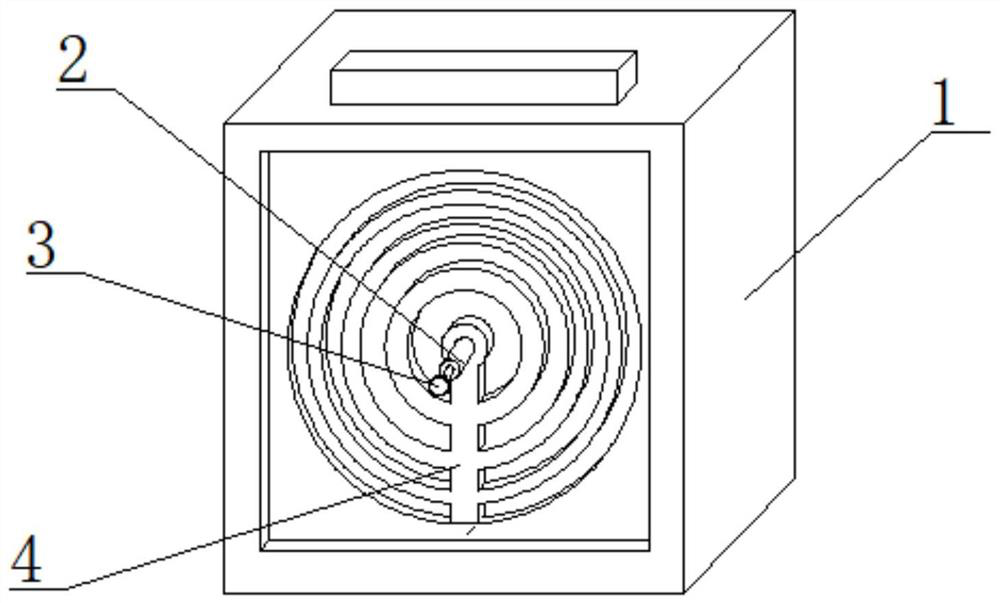
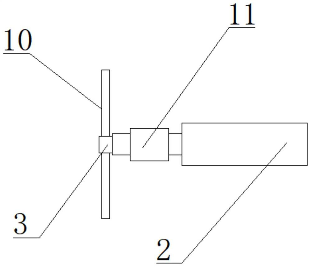
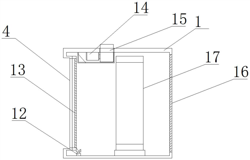
The invention relates to the technical field of ion fans, in particular to a direct current type ion fan which comprises a shell, an air frame is mounted in the shell, an ion fan is mounted in the air frame, a filter screen is mounted at the front end of the shell, a grating is fixed to the front end of the filter screen, and an electric push rod is fixedly mounted at the bottom of the rear end of the filter screen. The top of the electric push rod is provided with a scraper blade, the top in the shell is provided with an air draft pump, the air draft pump communicates with a dust box, the middle of the front end of the grating is provided with a shaft body, the end of the shaft body is connected with fan blades through a bearing, and the outer wall of the shaft body is provided with a rotating speed sensor. The motor drives the rotating disc to rotate so that the air frame rotates, meanwhile, the sliding point of the rotating disc slides in the limiting groove of the limiting frame, limiting is formed through the two sets of limiting clamps, and the direction of the air frame is adjusted, so that the charge movement direction is improved, dead corners are reduced, and the electrostatic elimination effect is improved.

Description

technical field [0001] The invention relates to the technical field of ion blowers, in particular to a direct current type ion blower. Background technique [0002] Ion blower static eliminator is a kind of static eliminator that transports ionized air to a distant place to eliminate static electricity; it is mainly composed of corona discharger, high voltage power supply and air supply system. [0003] The existing patent (announcement number is CN201911419729.1) and a double air duct shell structure for an ion fan, on the basis of the original single air duct in this patent, the wind is diverted to form a second air duct, and the sealing plate plays a role. The function of sealing is to control the opening and closing of the sealing plate under the fixing of the internal structure of the shell. The double-air duct shell structure of the ion fan has the advantages of double air ducts. In the actual use process, it provides users with a second air It is convenient for users...

Claims


Application Information

Patent Timeline
IPC IPC(8): F04D25/06F04D29/52F04D29/64F04D29/70F04D27/00H05F3/06
CPCF04D25/06F04D29/522F04D29/644F04D29/703F04D27/001H05F3/06Y02B30/70
Inventor 张智溪
Owner 苏州通格电子设备有限公司
Learn More