Fan frame structure

A frame structure and fan technology, applied in liquid fuel engines, parts of pumping devices for elastic fluids, non-variable pumps, etc., can solve problems such as easy increase in cost

Pending Publication Date: 2020-10-16
ASIA VITAL COMPONENTS SHENZHEN CO LTD
View PDF8 Cites 0 Cited by
  • Summary
  • Abstract
  • Description
  • Claims
  • Application Information

AI Technical Summary

Problems solved by technology

[0002] The noise generated by the fan when it is running has always been one of the many problems to be improved in the field of fans. Whether it is controlling the speed through the circuit, or changing the structure of the fan to improve the noise of the fan, it is a technical means to solve the problem in the existing technology. Among them, in In the existing

Method used


Image

  • Fan frame structure
  • Fan frame structure
  • Fan frame structure

Examples


Embodiment Construction

[0022] The above-mentioned purpose of the present invention and its structural and functional characteristics will be described according to the preferred embodiments of the accompanying drawings.

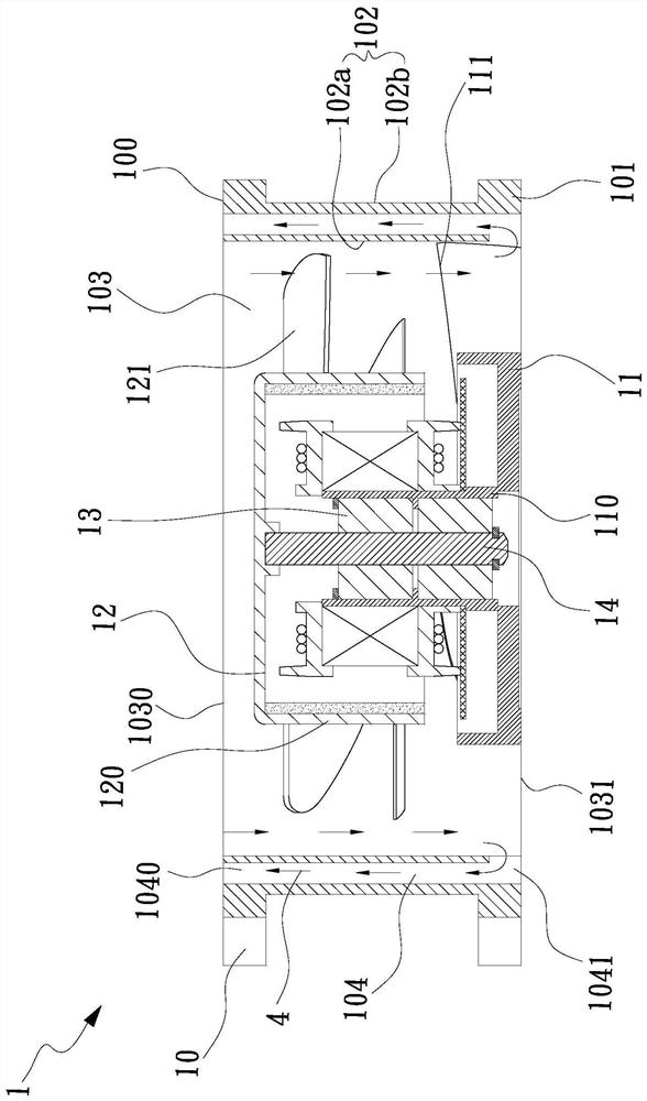
[0023] see figure 1 , is a cross-sectional view of the first embodiment of the fan frame structure of the present invention, as shown in the figure, a fan frame structure 1 includes a first frame body 10, and the first frame body 10 has a first upper end 100, A first lower end 101, a first frame wall 102 and a first main channel 103, the first main channel 103 runs through the first frame body 10 and is formed at the first upper end 100 and the first lower end 101 respectively A first main entrance 1030 and a first main exit 1031 .

[0024] The frame wall of the aforementioned first frame wall 102 is provided with a first sub-runner 104, the first sub-runner 104 is parallel to the first main channel 103 at intervals, and the first sub-runner 104 is located in the first main channe...


PUM


Abstract

The invention provides a fan frame structure which comprises a first frame. The first frame is provided with a first upper end, a first lower end, a first frame wall and a first main runner, the firstmain runner penetrates through the first frame and forms a first main inlet and a first main outlet at the first upper end and the first lower end correspondingly, a first auxiliary runner parallel to the first main runner is arranged in the first frame wall, the first auxiliary runner is located on the outer side of the first main runner and is provided with a first auxiliary outlet and a firstauxiliary inlet, the first auxiliary outlet is located in the first upper end of the first frame and is parallel to and adjacent to the first main inlet, the first auxiliary inlet is adjacent to the first lower end of the first frame and communicated with the first main runner, airflow can be guided to be jetted towards the first main inlet through the arrangement of the first auxiliary runner, and then the effects of noise reduction and airflow increase are achieved.

Description

technical field [0001] The invention relates to the field of cooling fans, in particular to a fan frame structure capable of guiding the high-pressure jet flow generated at the outlet of the fan to the inlet to achieve multiple noise reductions. Background technique [0002] The noise generated by the fan when it is running has always been one of the many problems to be improved in the field of fans. Whether it is controlling the speed through the circuit, or changing the structure of the fan to improve the noise of the fan, it is a technical means to solve the problem in the existing technology. Among them, in In the existing technology, the United States Patent Publication No. US6244817 discloses a method of only setting jet flow on the frame wall of the moving blade or stationary blade of the fan to suppress the vortex, but it needs to add an external jet source, which cannot be implemented in a limited space. And it is also easy to increase the cost of additional jet sou...

Claims


Application Information

Patent Timeline
IPC IPC(8): F04D29/52F04D29/54F04D29/66F04D25/08F04D25/16
CPCF04D25/08F04D25/166F04D29/522F04D29/541F04D29/663F04D29/667
Inventor 孙颂伟周初宪林宜緻李培全
Owner ASIA VITAL COMPONENTS SHENZHEN CO LTD
Why Eureka
Try Eureka