Nylon roller, motion door mechanism, vehicle and manufacturing technology

A nylon wheel and moving door technology, applied in vehicle parts, building structures, doors, etc., can solve problems such as falling off, and achieve the effects of stable performance, small footprint, and stress dispersion.

Pending Publication Date: 2020-10-16
南京盛兴茂机械设备制造有限公司
View PDF0 Cites 0 Cited by
  • Summary
  • Abstract
  • Description
  • Claims
  • Application Information

AI Technical Summary

Problems solved by technology

[0004] In view of this, the present invention provides a nylon roller to solve the technical problem that the existing nylon roller falls off due to the large deformation of the nylon wheel body relative to the bearing under load

Method used


Image

  • Nylon roller, motion door mechanism, vehicle and manufacturing technology
  • Nylon roller, motion door mechanism, vehicle and manufacturing technology
  • Nylon roller, motion door mechanism, vehicle and manufacturing technology

Examples


Embodiment 1

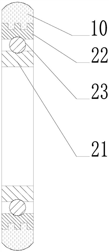
[0041] Such as figure 1 As shown, this embodiment provides a nylon roller, which includes a nylon wheel body 10 and a bearing 20 . The bearing 20 includes a bearing inner ring 21 and a bearing outer ring 22 that can rotate relative to the bearing inner ring 21 , and the surface of the bearing outer ring 22 facing away from the bearing inner ring 21 is the outer ring surface 221 of the bearing 20 . Such as Image 6 with Figure 7 As shown, knurling 25 is formed on the outer ring surface 221 of the bearing 20 . Such as figure 2 with image 3 As shown, the outer ring surface 221 of the bearing 20 is formed with a groove 24 sunken toward the inner ring 21 of the bearing; the nylon wheel body 10 is connected to the bearing 20 through the outer ring surface 221 of the bearing 20 .

[0042] The nylon roller in this embodiment adopts the bearing 20 as the main frame structure to realize the function of rolling. Such as figure 1 As shown, the bearing 20 includes a bearing inne...

Embodiment 2

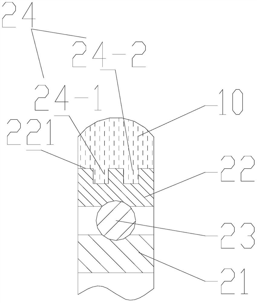
[0047] Such as figure 1 with figure 2 As shown, in this embodiment, the groove 24 surrounds the outer ring surface 221 of the bearing 20 along the circumferential direction of the outer ring surface 221 for a week. In this way, at any position in the circumferential direction of the bearing outer ring 22, a part of the nylon wheel body 10 can be embedded in the groove 24, so that each position of the nylon wheel body 10 can form a firm connection with the bearing outer ring 22. . In addition, the cross section of the groove 24 in this embodiment is rectangular (straight groove structure). The cross section of the groove 24 refers to a cross section parallel to the radial direction of the bearing 20 . The rectangular cross-section is easy to process, and the knurling 25 structure on the outer ring 22 of the bearing can eliminate the phenomenon of stress concentration, effectively preventing the nylon wheel body 10 from falling off when it is loaded and rolling.

Embodiment 3

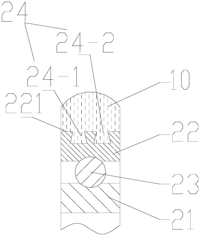
[0049] Such as image 3 As shown, the groove 24 of the nylon roller in this embodiment surrounds the outer ring surface 221 along the circumferential direction of the outer ring surface 221 of the bearing 20, and the width of the end of the groove 24 near the inner ring 21 of the bearing is greater than It is the width of the end away from the inner ring 21 of the bearing.

[0050] As a preferred embodiment, the groove 24 of this embodiment adopts an inverted "T"-shaped structure, that is, the bottom of the groove 24 (the part close to the axis of the bearing 20) is larger than the top of the groove 24 (closer to the outside of the bearing). The portion of the ring 22 face surface) is wide, so that the opening of the groove 24 is narrowed from the inside to the outside. With the structure of the aforementioned groove 24, the injection-molded nylon wheel body 10 is partially embedded in the groove 24. If the nylon wheel body 10 moves toward the direction away from the bearing ...


PUM


Abstract

The invention provides a nylon roller, a motion door mechanism, a vehicle and a manufacturing technology, and relates to the technical field of rollers. The nylon roller comprises a nylon roller bodyand a bearing. The bearing comprises a bearing inner race and a bearing outer race capable of rotating relative to the bearing inner race. The surface of the side, backing onto the bearing inner race,of the bearing outer race is the bearing outer race face. Knurls are formed on the bearing outer race face. A groove sunken into the bearing inner race is formed in the bearing outer race face. The nylon roller body is connected to the bearing through the bearing outer race. The nylon roller can effectively eliminate the phenomenon that a bearing is disengaged from the nylon roller body due to deformation generated by the load effect.

Description

technical field [0001] The invention relates to the technical field of rollers, in particular to a nylon roller, a moving door mechanism, a vehicle and a manufacturing process. Background technique [0002] Some door mechanisms implement door opening and closing by moving the door body, such as rail vehicle doors, elevator doors, wardrobe doors, and the like. And roller, as the key part of this type of movable door mechanism, has played an important role in the process of realizing the smooth movement of the door main body. Because the roller can bear a larger load during the process of rotating with the movement of the door body, and the nylon material has high mechanical strength and good toughness, so the current roller adopts a wheel body with a circle of nylon material fixed on the outer ring of the bearing. During the working process of the roller, the nylon wheel body rotates with the outer ring of the bearing, and contacts with other objects to bear a certain load. ...

Claims


Application Information

Patent Timeline
IPC IPC(8): F16C33/58F16C33/64E05D13/00B61D19/00B60J5/06B23P15/00
CPCB23P15/003B60J5/06B61D19/005E05D13/00F16C33/58F16C33/64
Inventor 徐功建
Owner 南京盛兴茂机械设备制造有限公司
Why Eureka
Try Eureka