Mobile signal lamp

A signal light and mobile technology, applied in the direction of instruments, traffic control systems, road vehicle traffic control systems, etc., can solve the problems of damage to the light body, low frequency of use of mobile signal lights, unfavorable emergency maintenance, etc., to reduce wear and tear, The effect of optimizing support stability and increasing static friction

Inactive Publication Date: 2020-10-16
周天健
View PDF0 Cites 2 Cited by
  • Summary
  • Abstract
  • Description
  • Claims
  • Application Information

AI Technical Summary

Problems solved by technology

[0003] When road traffic lights fail, emergency mobile signal lights are needed to maintain the traffic order at the intersection. The frequency of use of mobile signal lights is not high, and they are stored for a long time. Various accidental collisions will cause damage to the light body, and the emergency maintenance of traffic order is not used. Urgently need to design a kind of mobile signal light to solve the above problems

Method used


Image

  • Mobile signal lamp
  • Mobile signal lamp
  • Mobile signal lamp

Examples


Embodiment 1

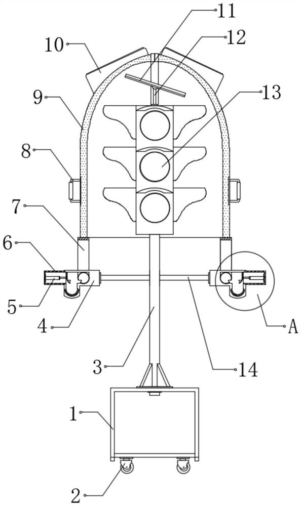
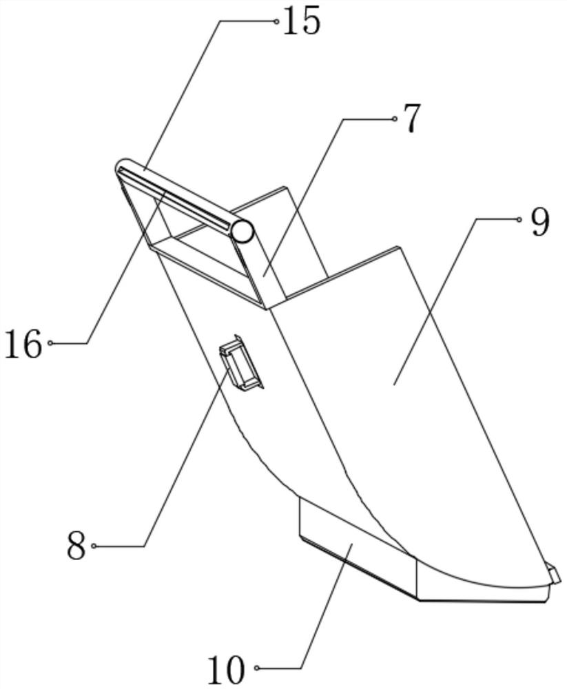
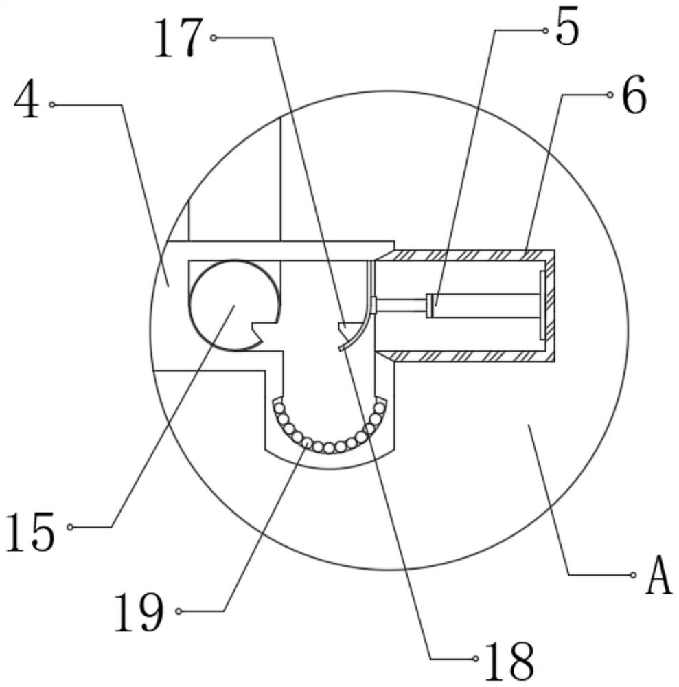
[0030] refer to Figure 1-4 , a mobile signal lamp, including a chassis 1, universal wheels 2 and a signal lamp 13, four universal wheels 2 are installed in the bottom of the chassis 1 in a rectangular shape, and the signal lamp 13 is arranged above the chassis 1, at the middle of the top of the chassis 1 The light pole 3 is connected by bolts, and the signal light 13 is fixedly connected to the top of the light pole 3, the two sides of the top of the light pole 3 are welded with connecting rods 14, and the ends of the two connecting rods 14 are fixedly connected with a card slot 4. The card slot 4 is set in an "L" shape, and the inside of the two card slots 4 is clamped with a rotating shaft 15, the top of the rotating shaft 15 is fixedly connected with the fixing frame 7, and the top of the fixing frame 7 is fixedly connected with the shield 9, And the signal lights 13 are located inside the two shields 9, and the tops of the two card slots 4 on the side away from each other...

Embodiment 2

[0039] refer to Figure 5 , a mobile signal lamp. Compared with Embodiment 1, the interior of the leg 10 is opened as a cavity, and the inner wall of the leg 10 is slidably connected with an iron plate 21, and one side of the top of the iron plate 21 is fixedly connected with an insertion rod. 22, the top of the insertion rod 22 is plugged with an insertion sleeve 20, the inside of the insertion sleeve 20 is provided with a spring 23, the bottom of the spring 23 is fixedly connected with the top of the insertion rod 22, the insertion sleeve 20 is fixedly connected with the outer wall of the shield 9, and the protection The outer wall of the cover 9 bottom is fixedly connected with an electromagnet 24, and the iron core of the electromagnet 24 is attached to the top of the iron plate 21.

[0040] Working principle: After the foot 10 touches the ground, the electromagnet 24 is powered off, and the spring 23 in the compressed state pushes the insertion rod 22 and the iron plate 2...


PUM


Abstract

The invention discloses a mobile signal lamp that comprises a case, universal wheels and a signal lamp; the four universal wheels are installed at the bottom of the case in a rectangular shape; the signal lamp is arranged above the case, the middle position of the top of the case is connected with a lamp pole through a bolt, the signal lamp is fixedly connected to the top of the lamp pole, connecting rods are welded to the two sides of the top of the lamp pole, clamping grooves are fixedly connected to the ends, away from each other, of the two connecting rods, and the clamping grooves are arranged to be in an L shape. In use, two shields close, the positioning mechanism is used for positioning the shield and the rotating shaft, the signal lamp in the shield is prevented from being damagedby accidental collision; during use, the push rod motor drives the clamping plate to retract into the box body and the rotating shaft to slide into the bottom of the clamping groove, and the shield is turned over, so that the bottom of the shield touches the ground to support and reinforce the signal lamp, the utilization value of the shield is brought into full play, and normal work of the signal lamp is not affected.

Description

technical field [0001] The invention relates to the technical field of traffic facilities, in particular to a mobile signal lamp. Background technique [0002] At present, road traffic lights are a category of traffic safety products. They are an important tool to strengthen road traffic management, reduce traffic accidents, improve road use efficiency, and improve traffic conditions. Applicable to intersections such as crosses and T-shaped intersections, it is controlled by road traffic signal controllers to guide vehicles and pedestrians to pass safely and orderly. [0003] When road traffic lights fail, emergency mobile signal lights are needed to maintain the traffic order at the intersection. The frequency of use of mobile signal lights is not high, and they are stored for a long time. Various accidental collisions will cause damage to the light body, and the emergency maintenance of traffic order is not used. Need to design a kind of mobile signal lamp badly to solve ...

Claims


Application Information

Patent Timeline
Patent Type & Authority Applications(China)
IPC IPC(8): G08G1/0955
CPCG08G1/0955
Inventor 周天健
Owner 周天健
Why Eureka
Try Eureka