Fuel cell hydrogen ejector and hydrogen circulating system thereof

A fuel cell and ejector technology, applied in fuel cells, fuel cell additives, electrical components, etc., to achieve the effect of less pipeline connections, fewer leakage points, and increased flow

Pending Publication Date: 2020-10-16
SHANGHAI FUEL CELL VEHICLE POWERTRAIN
View PDF0 Cites 10 Cited by
  • Summary
  • Abstract
  • Description
  • Claims
  • Application Information

AI Technical Summary

Problems solved by technology

[0005] The purpose of the present invention is to provide a fuel cell hydrogen ejector and its hydrogen circulation system, which solves the technical problem of convenient regulation of the ejection amount

Method used


Image

  • Fuel cell hydrogen ejector and hydrogen circulating system thereof
  • Fuel cell hydrogen ejector and hydrogen circulating system thereof
  • Fuel cell hydrogen ejector and hydrogen circulating system thereof

Examples


Embodiment 1

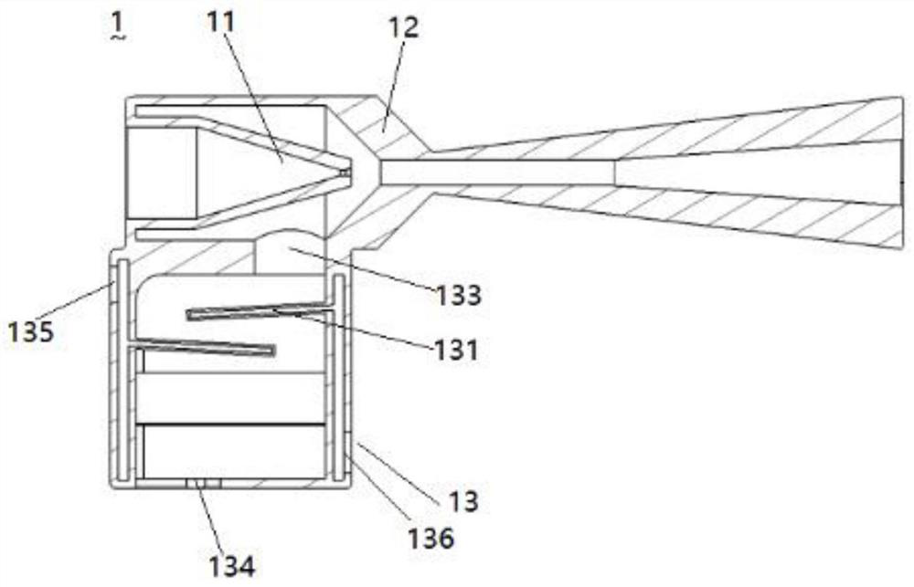
[0035] Such as figure 1 As shown, a fuel cell hydrogen ejector includes a nozzle 11, an ejector main body 12 and a control main body 13; the ejector main body 12 includes a suction chamber, a mixing chamber and a diffusion chamber arranged in sequence; one side of the suction chamber is provided with There is a primary inlet for the inflow of high-pressure hydrogen, and a mixed gas outlet for the outflow of the mixed gas is provided on one side of the diffusion chamber; the nozzle 11 is located in the suction chamber; the control body 13 is provided with a refrigerant channel and a mixed cooling channel; the refrigerant channel is used for refrigerant Circulation; the mixed cooling channel is used for heat exchange and cooling of the high-temperature hydrogen-water vapor mixture discharged from the stack 2 and the refrigerant; the mixed cooling channel communicates with the suction chamber.

[0036] In actual use, the ejector main body 12 is arranged horizontally, and a nozzle...

Embodiment 2

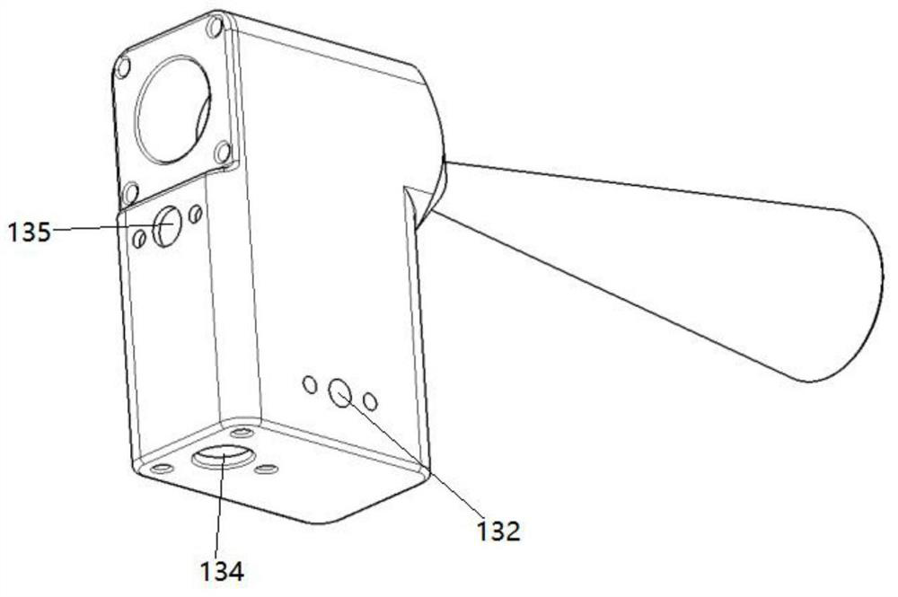
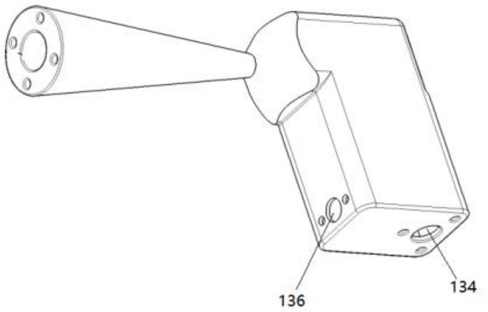
[0047] On the basis of Example 1, such as Figure 4 As shown, the hydrogen circulation system with the fuel cell hydrogen injector 1 includes the hydrogen injector 1 and the electric stack 2; the mixed gas outlet of the hydrogen injector 1 is connected to the electric stack 2 through the first pipeline; The hydrogen inflow inlet 132 is connected to the cell stack 2 through a second pipeline; a third pipeline connected externally between the outlet 135 and the inlet 136 of the refrigerant passage.

[0048] In a certain embodiment, the primary inflow port is externally connected with a fourth pipeline; the fourth pipeline is provided with a pressure control valve 6; the third pipeline is provided with a compressor 3, a condenser 4 and a throttle valve 5; the drain port 134 There is a drain valve.

[0049] In a certain embodiment, the compressor 3 , the condenser 4 and the throttle valve 5 are arranged in sequence along the fluid flow direction.

[0050] In actual use, the pres...


PUM


Abstract

The invention belongs to the technical field of fuel cells, and discloses a fuel cell hydrogen ejector and a hydrogen circulating system thereof. The fuel cell hydrogen ejector comprises a nozzle, anejector main body and a regulation and control main body, wherein the ejector main body comprises a suction chamber, a mixing chamber and a diffusion chamber which are communicated in sequence; a primary flow inlet for high-pressure hydrogen to flow in is formed in one side of the suction chamber, and a mixed gas outlet for mixed gas to flow out is formed in one side of the diffusion chamber; thenozzle is arranged in the suction chamber; the regulation and control main body is provided with a refrigerant channel and a mixed cooling channel; the refrigerant channel is used for circulation of arefrigerant; the mixed cooling channel is used for carrying out heat exchange cooling on high-temperature hydrogen and water vapor mixed gas discharged from a galvanic pile and a refrigerant; and themixed cooling channel is communicated with the suction chamber. According to the fuel cell hydrogen ejector, the temperature difference and the flow of the refrigerant are regulated and controlled, so that the condensation amount of water vapor can be controlled, the hydrogen proportion is controlled, and the amount of the hydrogen ejector is increased from integrated drainage.

Description

technical field [0001] The invention belongs to the technical field of fuel cells, in particular to a fuel cell hydrogen injector and a hydrogen circulation system thereof. Background technique [0002] In recent years, under the background of the global response to energy conservation, emission reduction and the use of clean energy, major countries and regions have paid more and more attention to the development and utilization of hydrogen energy, and gradually included hydrogen energy in relevant development strategies and industrial policies. As its main carrier, the automobile industry has received great attention. The domestic hydrogen fuel cell industry is developing vigorously under the fierce stimulus of policies and markets. [0003] In the design of the fuel cell system, in the hydrogen supply system, due to the different working conditions of the stack, the requirements for the metering ratio of hydrogen are different, and in order to ensure high efficiency, the ...

Claims


Application Information

Patent Timeline
Patent Type & Authority Applications(China)
IPC IPC(8): H01M8/04089H01M8/04082H01M8/04119H01M8/04223H01M8/04228H01M8/04303H01M8/04701H01M8/04746H01M8/04828
CPCH01M8/04097H01M8/04104H01M8/04164H01M8/04201H01M8/04253H01M8/04708H01M8/04753H01M8/04835H01M8/04228H01M8/04303Y02E60/50
Inventor 胡章胜郭伟静李仕栋何雍吴兵
Owner SHANGHAI FUEL CELL VEHICLE POWERTRAIN
Why Eureka
Try Eureka