Control method, device and terminal equipment of multi-energy coupling system

A technology of coupling system and control method, which is applied in the direction of circuit devices, power lines, transportation and packaging, etc., can solve the problems of poor power quality, waste of regenerative braking energy, etc., to solve the problems of poor power quality and waste of regenerative braking energy Effect

Active Publication Date: 2021-03-23
DUNSHI MAGNETIC ENERGY TECH
View PDF6 Cites 0 Cited by
  • Summary
  • Abstract
  • Description
  • Claims
  • Application Information

AI Technical Summary

Problems solved by technology

[0003] In view of this, the embodiment of the present invention provides a control method, device and terminal equipment of a multi-energy coupling system to solve the problems of poor power quality and waste of regenerative braking energy in the traction power supply system in the prior art

Method used


Image

  • Control method, device and terminal equipment of multi-energy coupling system
  • Control method, device and terminal equipment of multi-energy coupling system
  • Control method, device and terminal equipment of multi-energy coupling system

Examples


Embodiment Construction

[0019] In the following description, specific details such as specific system structures and technologies are presented for the purpose of illustration rather than limitation, so as to thoroughly understand the embodiments of the present invention. It will be apparent, however, to one skilled in the art that the invention may be practiced in other embodiments without these specific details. In other instances, detailed descriptions of well-known systems, devices, circuits, and methods are omitted so as not to obscure the description of the present invention with unnecessary detail.

[0020] In order to illustrate the technical solutions of the present invention, specific examples are used below to illustrate.

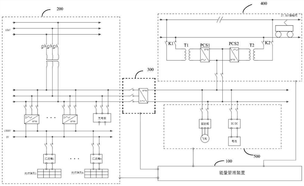
[0021] In one embodiment of the present invention, as figure 1 as shown, figure 1 The structure of the multi-energy coupling system provided by the embodiment of the present invention is shown, which includes:

[0022] Energy management device 100, new energy power g...


PUM


Abstract

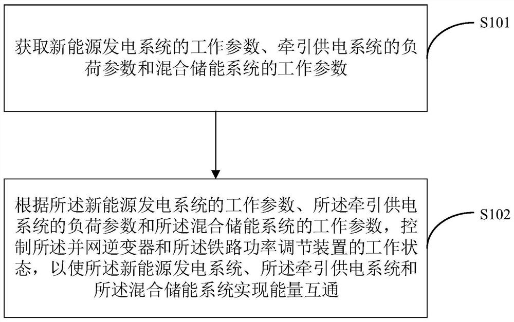
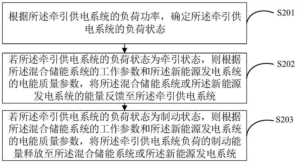
The invention is applicable to the technical field of power grids, and provides a control method and device of a multi-energy coupling system and terminal equipment, and the method comprises the steps: obtaining an electric energy quality parameter of a new energy power generation system, a load parameter of a traction power supply system and a working parameter of a hybrid energy storage system;and according to the electric energy quality parameter of the new energy power generation system, the load parameter of the traction power supply system and the working parameter of the hybrid energystorage system, controlling the working states of a grid-connected inverter and a railway power adjusting device so as to enable the new energy power generation system, the traction power supply system and the hybrid energy storage system to realize energy intercommunication. Energy intercommunication among the new energy power generation system, the traction power supply system and the hybrid energy storage system can be achieved, the problems that the traction power supply system is poor in electric energy quality and regenerative braking energy is wasted can be solved, and the electric energy quality problem of new energy power generation can also be solved.

Description

technical field [0001] The invention belongs to the technical field of electrified railways and power grids, and in particular relates to a control method, device and terminal equipment of a multi-energy coupling system. Background technique [0002] Electrified railway, also known as electrified railway, is a railway that is mainly run by electric locomotives or EMUs, two types of railway trains (that is, commonly known as trains). Electrified railways are large-scale industrial users with distinctive characteristics, and the traction power supply system, as a typical impact load, has always had an impact on the national grid. At present, the main problems in the traction power supply system of electrified railways include: high basic electricity expenses, waste of regenerative braking energy, poor power quality, and low capacity utilization of traction transformers. Contents of the invention [0003] In view of this, the embodiments of the present invention provide a co...

Claims


Application Information

Patent Timeline
Patent Type & Authority Patents(China)
IPC IPC(8): H02J3/30H02J3/32H02J3/38B60M3/00B60M3/02
CPCB60M3/00B60M3/02H02J3/30H02J3/381H02J3/322H02J2300/24H02J2300/28H02J2310/48Y02E10/56Y02E60/16
Inventor 陈鹰王大杰唐英伟李胜飞任静张建平李玉光王存岗
Owner DUNSHI MAGNETIC ENERGY TECH
Why Eureka
Try Eureka