Rear single-propeller foldable type composite wing aircraft with propeller thrust composite auxiliary wings

A propeller and composite wing technology, applied in the field of aircraft, can solve the problems of high take-off and landing requirements, low safety factor, low safety factor, etc., and achieve the effect of reducing gravitational acceleration, high wing structure strength, and safeguarding personnel and objects.

Inactive Publication Date: 2018-09-07
JIANGSU CHANGTAN ROBOT CO LTD
View PDF5 Cites 0 Cited by
  • Summary
  • Abstract
  • Description
  • Claims
  • Application Information

AI Technical Summary

Problems solved by technology

The traditional fixed wing has the advantages of fast flight speed, low energy consumption, etc., but it has the disadvantages that the main wing and the horizontal tail are not connected front and rear, the wing structure is not strong, easy to be damaged, the take-off and landing requirements are high, and the take-off and landing distance is long; the traditional vertical The take-off and landing aircraft has the advantages of convenient take-off and landing, but has the disadvantages of high energy consumption, low safety factor, poor load capacity, slow horizontal flight speed, and easy crash; although the current vertical take-off and landing fixed wing has the characteristics of convenient take-off and landing , but the controllability is not ideal when flying horizontally, and there are disadvantages such as large flight resistance, high energy consumption, and low safety factor.

Method used


Image

  • Rear single-propeller foldable type composite wing aircraft with propeller thrust composite auxiliary wings
  • Rear single-propeller foldable type composite wing aircraft with propeller thrust composite auxiliary wings
  • Rear single-propeller foldable type composite wing aircraft with propeller thrust composite auxiliary wings

Examples


Embodiment Construction

[0035] The present invention will be further described below in conjunction with the drawings.

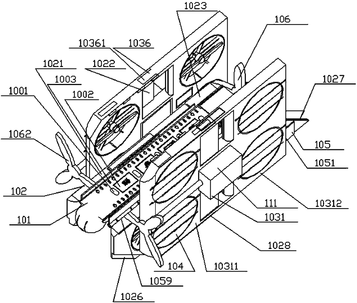
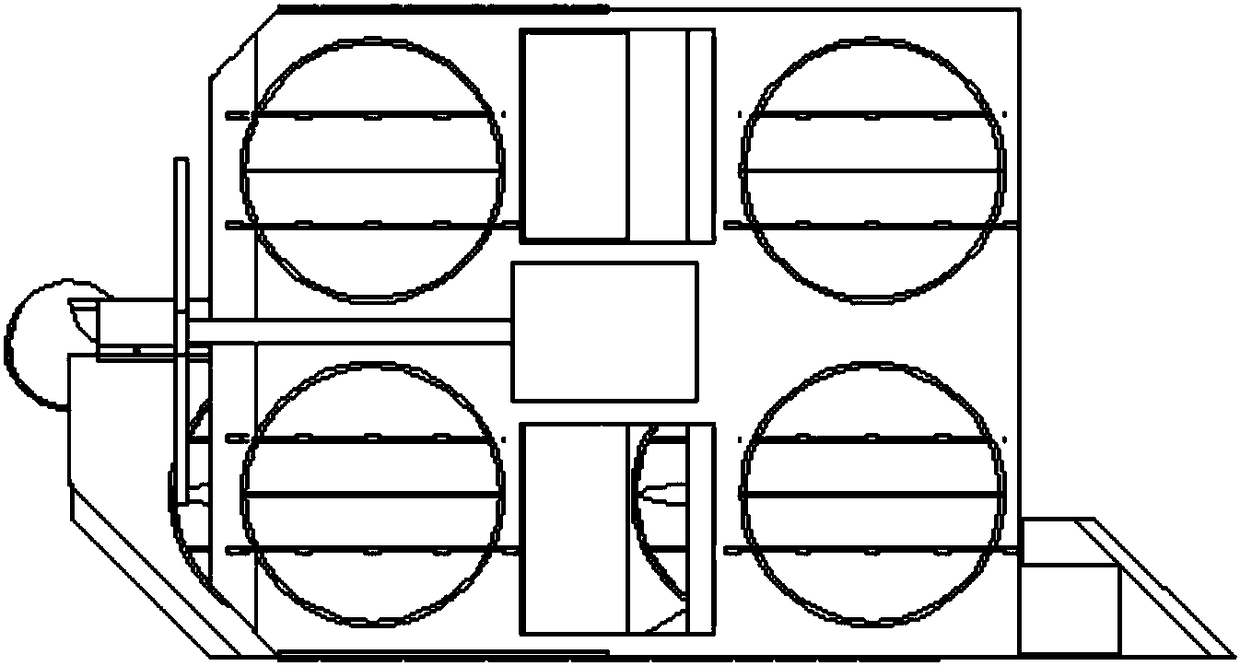
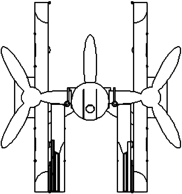
[0036] Such as Figure 1 to Figure 5 As shown, the rear single-propeller foldable composite wing aircraft with propeller thrust composite ailerons includes a rear single-propeller composite wing aircraft, and propeller thrust self-powered composite ailerons assembled on both sides of its wing; wherein, the The rear single-propeller composite wing aircraft includes a body 101, a composite lift wing 102 foldably installed on both sides of the body 101, and a propeller 106; wherein the body 101 is set as a deck platform; the composite lift wing 102 Built-in self-enclosed ducted fan 104, the outer side of the composite lift wing 102 is designed with a wing hinge 1028; the front end of the propeller thrust self-powered composite wing is provided with a propeller 1062, and the propeller thrust self-powered composite wing is provided with The self-enclosed ducted fan 104 has an electro-hydr...


PUM


Abstract

The invention provides a composite lift force aircraft with an expansion platform. The aircraft is composed of a rear single-propeller type composite wing aircraft and propeller thrust self-energy-supply composite auxiliary wings assembled on the two sides of the rear single-propeller type composite wing aircraft. The rear single-propeller type composite wing aircraft comprises an aircraft body, composite lift force wings installed on the two sides of the aircraft body in a foldable mode and a propeller thruster, wherein the aircraft body is arranged to be a deck platform; self-sealed ducted fans are arranged in the composite lift force wings, and wing hinges are arranged on the outer sides of the composite lift force wings; and self-sealed ducted fans are arranged in the propeller thrustself-energy-supply composite auxiliary wings, electro-hydraulic-gas ports and wing hinges are arranged on one side or two sides of each propeller thrust self-energy-supply composite auxiliary wing, and the propeller thrust self-energy-supply composite auxiliary wings are movably connected with the composite lift force wings through the wing hinges. The aircraft has the beneficial effects that thetake-off and landing distance is short, the flight speed is high, the wing structural strength is high, the wings can store energy, the auxiliary wings adopt composite lift force and have propeller power, the flight energy consumption is low, the aerial duration time is long, and safety is high.

Description

Technical field [0001] The invention relates to an aircraft, in particular to a rear single-propeller foldable composite wing aircraft with a propeller thrust composite aileron, belonging to the technical field of aircraft equipment. Background technique [0002] Existing aircraft are mainly divided into two categories: fixed-wing and vertical take-off and landing aircraft (such as helicopters and multi-rotors). Of course, there is also a vertical take-off and landing fixed wing product. The traditional fixed wing has the advantages of fast flight speed, low energy consumption, etc., but the main wing and the horizontal tail are not connected before and after, the wing structure is not strong, easy to damage, high take-off and landing requirements, and long take-off and landing distances; the traditional vertical Take-off and landing aircraft have the advantages of convenient take-off and landing, but they have disadvantages such as high energy consumption, low safety factor, po...

Claims


Application Information

Patent Timeline
Patent Type & Authority Applications(China)
IPC IPC(8): B64C27/28B64C3/00B64C3/56B64C5/10B64C11/00B64D27/02
Inventor 任曲波
Owner JIANGSU CHANGTAN ROBOT CO LTD
Why Eureka
Try Eureka