A 3D printing system for materials in a microgravity environment

A 3D printing and microgravity technology, applied in the field of material 3D printing systems in a microgravity environment, can solve the problems of unfavorable 3D printing, easy spheroidization, etc., to improve 3D printing quality, reduce thermal stress, and achieve strong robustness. Effect

Active Publication Date: 2021-08-10
SHANGHAI UNIV
View PDF5 Cites 0 Cited by
  • Summary
  • Abstract
  • Description
  • Claims
  • Application Information

AI Technical Summary

Problems solved by technology

[0007] In view of the fact that fluid materials in microgravity environment are easy to spheroidize due to surface tension and viscous force in the prior art, which is not conducive to 3D printing, the purpose of the present invention is to provide a 3D printing system for materials in microgravity environment, and adopt a new method to solve the problem of microgravity. 3D printing problems of fluid materials in ambient environment

Method used


Image

  • A 3D printing system for materials in a microgravity environment
  • A 3D printing system for materials in a microgravity environment
  • A 3D printing system for materials in a microgravity environment

Examples


Embodiment 1

[0032]This embodiment is applied to 3D printing of materials in a closed atmospheric environment, and the working environment is a manned spacecraft or a space station in a closed atmospheric environment. The manned spacecraft or space station in orbit is a closed cabin in an atmospheric environment. Under the action of microgravity, the fluid in the cabin is easy to form a spherical shape; in addition, the gas and other emissions generated during the material 3D printing process will seriously affect the artificial The quality of the atmospheric environment brings a series of safety hazards.

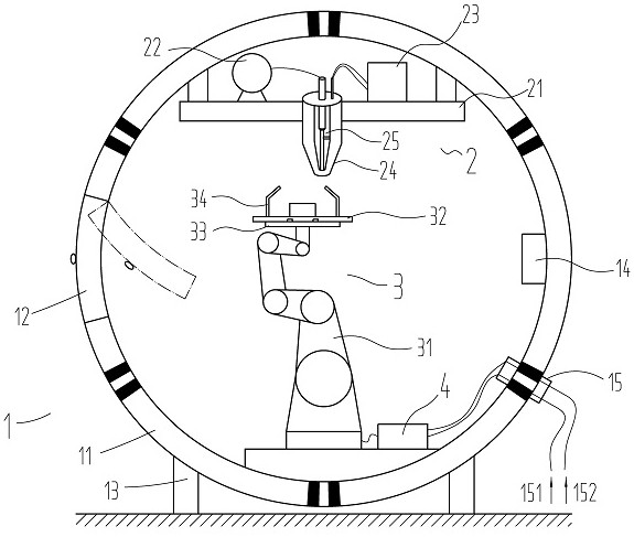
[0033] like figure 2 As shown in the figure, a material 3D printing system in a microgravity environment works in a sealed system that is insulated from the external environment and protected by an inert atmosphere of the internal environment, including a space capsule 1, a print head subsystem 2, a printing platform subsystem 3, and a control subsystem. 4. The space capsule 1 is used...

Embodiment 2

[0045] This embodiment is applied to 3D printing of materials in an open space environment. In a space base (such as a moon base) directly exposed to a vacuum environment, the 3D printing system is not only exposed to cosmic radiation, but also in an ultra-low temperature working environment. This places extremely high demands on the 3D printing system.

[0046] The material 3D printing system in the microgravity environment works in the airtight box of the space capsule 1 . The airtight box 11 is installed on the ground of the space base through the box fixing feet 13 , and is connected to the electrical interface equipped with the space base through the external interface 15 . The 3D printing system has a certain temperature and pressure inside during operation. The spherical shell can prevent the airtight box 11 from being deformed under the action of air pressure, and the double-layer thermal insulation structure can prevent the system heat loss caused by the vacuum heat r...


PUM


Abstract

The invention discloses a material 3D printing system in a microgravity environment, belonging to the field of material 3D printing equipment. The system works in a sealed system that is thermally insulated from the external environment and protected by an inert atmosphere in the internal environment, including: space capsule, printing head subsystem, printing platform subsystem, and control subsystem. The inner surface of the upper part of the nozzle of the present invention is rough, which generates capillary force to drag the fluid to move in a directional direction, and the inner surface of the lower part of the nozzle is smooth, which is conducive to the accelerated movement of the fluid droplets; the negative pressure drive of the inert gas realizes the speed control of the fluid; the crystal oscillator rod realizes the movement of the fluid droplets. Size and volume control. The invention can be widely used in microgravity or no-gravity working environments such as manned spacecraft, space stations, space bases, and deep-sea submersibles.

Description

technical field [0001] The invention relates to the field of material 3D printing equipment, in particular to a material 3D printing system in a microgravity environment. It is suitable for microgravity or no-gravity 3D printing working environments such as manned spacecraft, space stations, space bases, and manned deep submersibles. Background technique [0002] With the development of science and technology, human beings have begun to go to outer space. In the future, the establishment of space stations in space or immigration bases on planets has been put on the agenda. The construction of space stations and bases requires the production of a large number of 3D printed products, especially high-strength 3D printed metal products, in a microgravity or no-gravity environment in space, so as to realize the rapid manufacture of tools and parts for space stations and space bases. [0003] At present, there are many ways to 3D print metal materials on the ground, most of which...

Claims


Application Information

Patent Timeline
Patent Type & Authority Patents(China)
IPC IPC(8): B22F3/115
CPCB22F3/115
Inventor 张金松孙嘉禾王志亮
Owner SHANGHAI UNIV
Why Eureka
Try Eureka