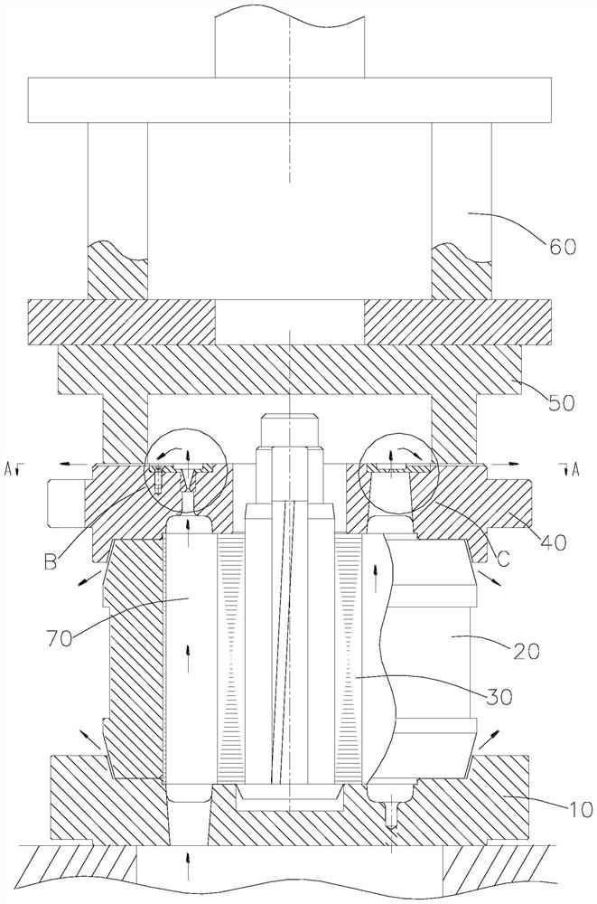
Die-casting mold for squirrel-cage motor rotor

A technology for motor rotors and die-casting molds, applied in the manufacture of squirrel cage rotors, stator/rotor bodies, etc., can solve the problems of low labor intensity, reduced motor efficiency, hidden dangers of motor performance efficiency, etc., to reduce labor intensity and improve production efficiency. Effect

Pending Publication Date: 2020-10-16
FOSHAN SHUNDE XINYUAN ELECTRIC
View PDF6 Cites 0 Cited by
  • Summary
  • Abstract
  • Description
  • Claims
  • Application Information

AI Technical Summary

Problems solved by technology

Because the speed of die-casting is too fast, it usually takes only a few tenths of a second to pour aluminum water into the rotor squirrel cage. In such a short period of time, it is difficult to discharge the gas in the cavity, resulting in the presence of Lots of stomata
Bring many hidden dangers to the performance of the motor (including noise, vibration, efficiency)
That is: the noise and vibration exceed the standard, and the efficiency of the motor is also reduced
Therefore, the die-casting method is adopted for the aluminum rotor of small motors. Although the efficiency is high and the labor intensity is low, the large number of air holes in the rotor guide bars and end rings is a common problem in the current motor manufacturing industry.

Method used


Image

  • Die-casting mold for squirrel-cage motor rotor
  • Die-casting mold for squirrel-cage motor rotor
  • Die-casting mold for squirrel-cage motor rotor

Examples


Embodiment Construction

[0025] The following will clearly and completely describe the technical solutions in the embodiments of the present invention with reference to the accompanying drawings in the embodiments of the present invention. Obviously, the described embodiments are only some, not all, embodiments of the present invention. Based on the embodiments of the present invention, all other embodiments obtained by persons of ordinary skill in the art without making creative efforts belong to the protection scope of the present invention.

[0026] It should be noted that when a component is said to be “fixed” to another component, it may be directly on the other component or there may be another intermediate component through which it is fixed. When a component is said to be "connected" to another component, it may be directly connected to the other component or there may be another intermediate component at the same time. When a component is said to be "set on" another component, it may be set d...


PUM

PropertyMeasurementUnit
diameteraaaaaaaaaa
heightaaaaaaaaaa

Abstract

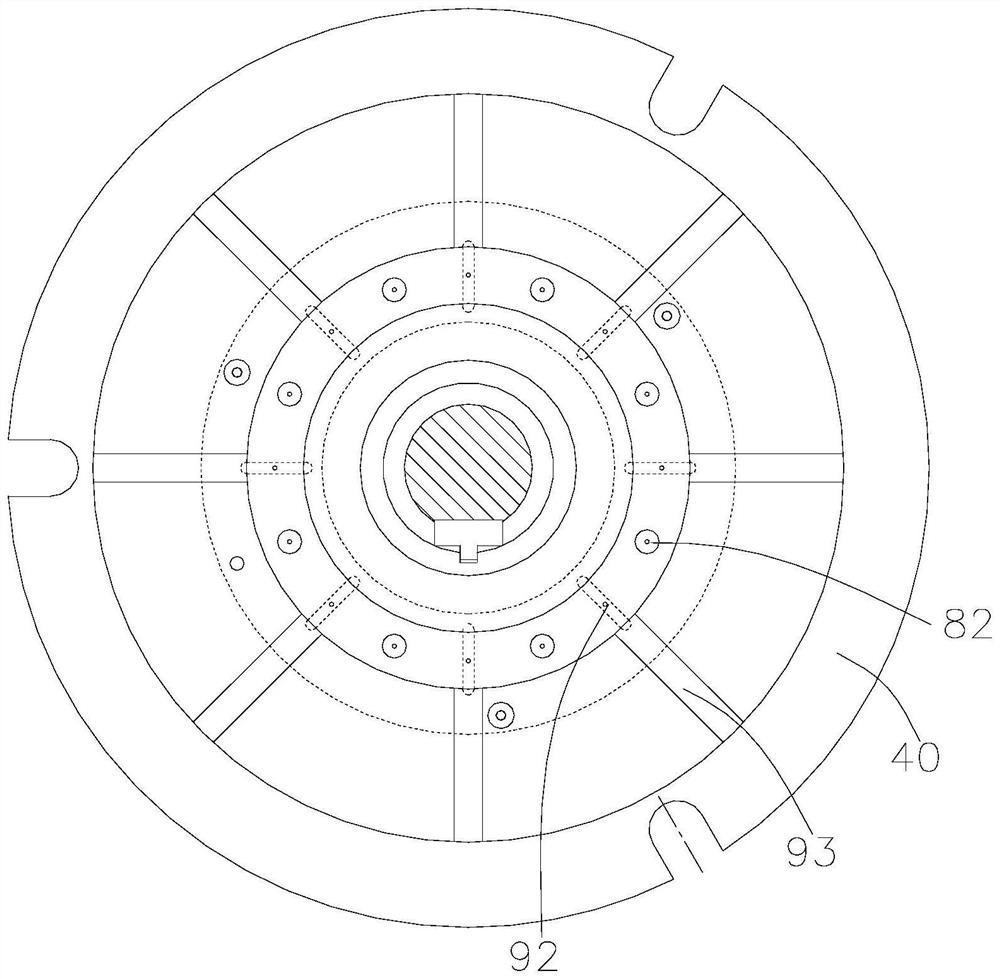
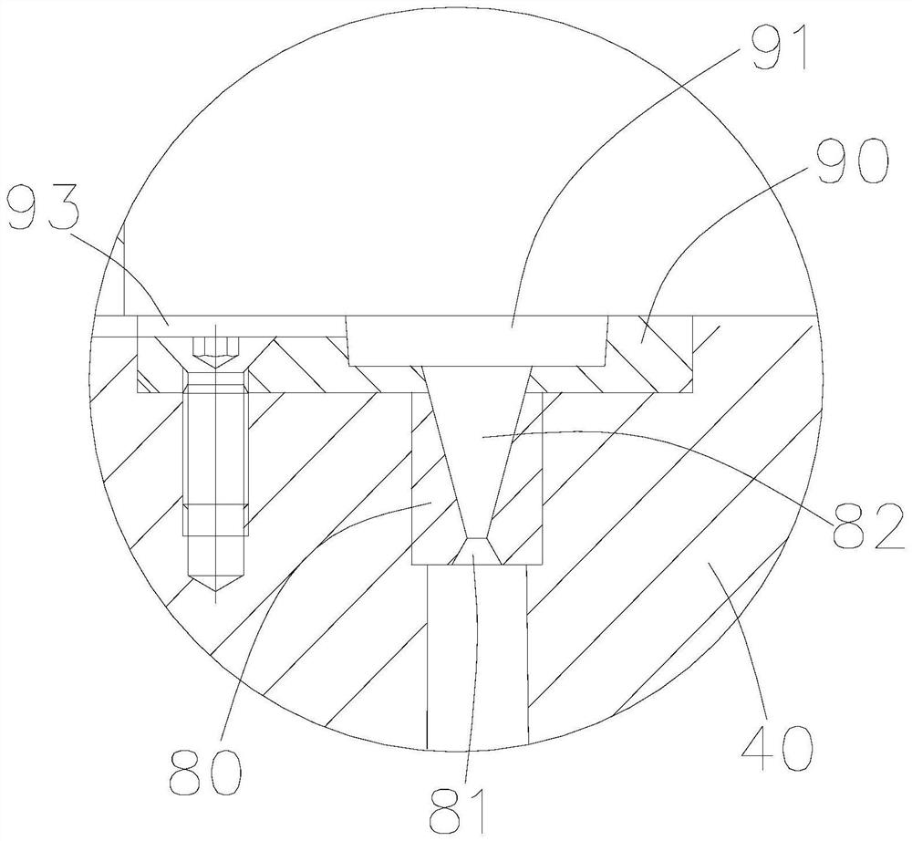
The invention discloses a die-casting mold for a squirrel-cage motor rotor. The mold comprises a lower blade mold, a middle mold, a rotor core and an upper blade mold; the middle mold clasps the rotorcore and is positioned on the lower blade mold; the upper blade mold is arranged on the middle mold; the lower blade mold, the rotor core and the upper blade mold jointly form a cavity (rotor cage).The die-casting mold further comprises a balance plunger (except H132 and below) and a pressing plate. The balance plunger is provided with a conical flow guide hole, the flow guide hole is communicated with the cavity, the pressing plate is provided with an overflow groove and an exhaust groove communicated with the overflow groove; the pressing plate is fixed to the upper blade mold body, the overflow groove is communicated with the flow guide hole, and the exhaust groove extends out of the upper blade mold body from the pressing plate. The taper hole is adopted for exhausting, so gas in thecavity is easily exhausted along the taper hole, and retention is avoided; an overflow groove structure is adopted, gas in a cavity is guided into an overflow groove, and the two effects are achievedthat firstly, pressure difference is formed inside and outside the cavity, the pressure outside the cavity is small, and gas does not flow back; and excessive overflowing aluminum skimmings can be accommodated in the accommodating space.

Description

technical field [0001] The invention relates to cast aluminum for a motor rotor, in particular to a squirrel-cage motor rotor die-casting mold. Background technique [0002] Generally, the squirrel-cage rotors of small motors are made of die-cast aluminum. After casting, the squirrel cages are required to be tight inside, with small and few air holes, so as to ensure high rotor dynamic balance accuracy and good motor performance. In the traditional die-casting mold, the upper leaf mold is connected with the upper template as a whole, and several exhaust grooves with a depth of about 0.2-0.5mm are opened on the joint surface of the two to discharge the gas in the cavity. Because the speed of die-casting is too fast, it usually takes only a few tenths of a second to pour aluminum water into the rotor squirrel cage. In such a short period of time, it is difficult to discharge the gas in the cavity, resulting in the presence of Lots of pores. It brings many hidden dangers to t...

Claims


Application Information

Patent Timeline
Patent Type & Authority Applications(China)
IPC IPC(8): H02K15/02B22D17/22
CPCH02K15/0012B22D17/22
Inventor 彭家强毛漂军
Owner FOSHAN SHUNDE XINYUAN ELECTRIC
Why Eureka
Try Eureka