Control system for mobile phone camera module detection

A mobile phone camera and control system technology, applied in the field of camera detection, can solve problems such as difficult to accurately judge the installation of the camera, and achieve the effect of improving accuracy

Inactive Publication Date: 2020-10-16
SHINE OPTICS TECH CO LTD
View PDF6 Cites 2 Cited by
  • Summary
  • Abstract
  • Description
  • Claims
  • Application Information

AI Technical Summary

Problems solved by technology

[0006] The invention provides a control system for detecting the camera module of a mobile phone, which solves the technical problem that it is difficult to accurately judge the installation situation of the camera in the prior art when the detection environment light is insufficient

Method used


Image

  • Control system for mobile phone camera module detection

Examples


Embodiment 1

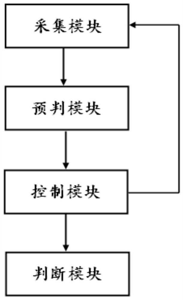
[0042] The embodiment of the control system used for mobile phone camera module detection in the present invention is basically as attached figure 1 shown, including:

[0043] The collection module is used to collect pictures of the camera module to be detected to obtain the collected pictures;

[0044] The pre-judgment module is used to judge whether the collected pictures meet the requirements according to preset standards;

[0045] The compensation module is used to perform light compensation when the collected picture does not meet the requirements, and after the light compensation is completed, send a command to re-collect the picture to the collection module; when the collected picture meets the requirements, send the collected picture;

[0046] The judging module is used to receive the collected picture, search for the edge contour of the camera area on the collected picture, and obtain the maximum value of the shape function gradient of the edge contour, if the maximu...

Embodiment 2

[0057] The only difference from Embodiment 1 is that the judging module also includes: a storage unit, such as a solid-state disk; a feature unit, such as MATLAB software; a position comparison unit and a position compensation unit, such as implemented by using relevant program codes in the prior art. A standard picture is obtained by photographing a qualified camera module through manual inspection, and then the feature information and position information of the characteristic area in the standard picture and the position information of the camera area in the standard picture are stored in advance. In order to make the edge profile search of the camera area more targeted, before searching the edge profile of the camera area, the position information of the feature area on the captured picture is first determined according to the feature information. After determination, in order to reduce the error in searching the edge contour of the camera area, it is necessary to correct t...


PUM


Abstract

The invention relates to the technical field of camera detection, in particular to a control system for mobile phone camera module detection. The system comprises an acquisition module, a pre-judgingmodule, a compensation module and a judgment module, wherein the acquisition module is used for acquiring a picture of a to-be-detected camera module to obtain an acquired picture; the pre-judging module is used for judging whether the acquired picture meets the requirement or not according to a preset standard; the compensation module is used for carrying out light compensation when the acquiredpicture does not meet the requirement; and the judgment module is used for receiving the acquired picture, searching the edge contour of the camera area on the acquired picture, acquiring the maximumvalue of the shape function gradient of the edge contour, judging that the camera is normally installed if the maximum value of the shape function gradient of the edge exceeds the preset standard gradient maximum value, and otherwise, judging that the camera is abnormally installed. Under the condition that ambient light is detected to be insufficient, collection can be conducted again after lightcompensation, and the technical problem that in the prior art, under the condition that ambient light is detected to be insufficient, accurately judging the installation condition of the camera is difficult is solved.

Description

technical field [0001] The invention relates to the technical field of camera detection, in particular to a control system for detection of camera modules of mobile phones. Background technique [0002] The camera module refers to the integrated component of the lens and the image processing circuit, which provides an interface for the smart terminal to transmit the captured image information. At present, basically all smartphones and tablet computers have a camera function, and the quality of the camera module directly affects the user's shooting experience. Therefore, before the camera module leaves the factory, its component parameters need to be inspected. For example, visual inspection is widely used. [0003] Visual inspection, that is, using machines instead of human eyes for measurement and judgment, converting the captured target into an image signal through an image capture device, and sending it to a dedicated image processing system; and then converting it into ...

Claims


Application Information

Patent Timeline
Patent Type & Authority Applications(China)
IPC IPC(8): H04N17/00
CPCH04N17/002
Inventor 卢绍杰
Owner SHINE OPTICS TECH CO LTD
Why Eureka
Try Eureka