Locking device for ventilator

A technology for locking devices and ventilators, applied to pump devices, components of pumping devices for elastic fluids, mechanical equipment, etc., can solve the problems of shortening the service life of components, being unable to measure, and being expensive

Active Publication Date: 2021-09-17
EBM PAPST ST GEORGEN & -
View PDF9 Cites 0 Cited by
  • Summary
  • Abstract
  • Description
  • Claims
  • Application Information

AI Technical Summary

Problems solved by technology

If the rotor rotates against the predetermined first direction of rotation, it is impossible or very difficult to determine the correct rotor position
[0003] In order to prevent the passive rotation of the rotor, the known implementations in the prior art propose to equip the ventilator with a mechanical brake, the ventilator thus becomes bulky and expensive
A known alternative is electric self-locking by means of a motor, but this creates a permanent load on the motor and motor electronics, reducing the service life of these components

Method used


Image

  • Locking device for ventilator
  • Locking device for ventilator
  • Locking device for ventilator

Examples


Embodiment Construction

[0030] The accompanying drawings are illustrative schematic diagrams. In the figures, the same reference signs refer to the same functional and / or structural features.

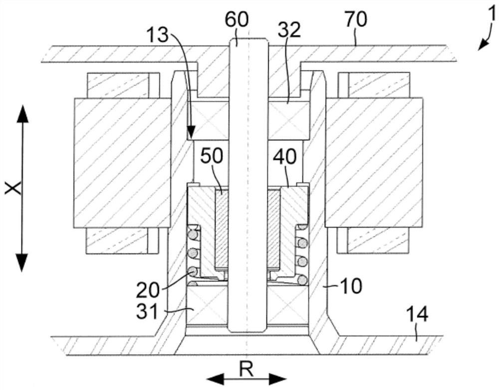
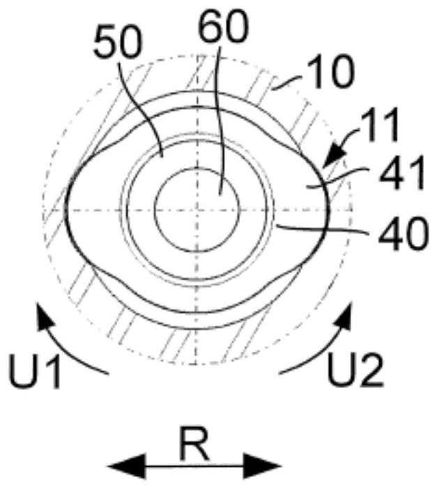
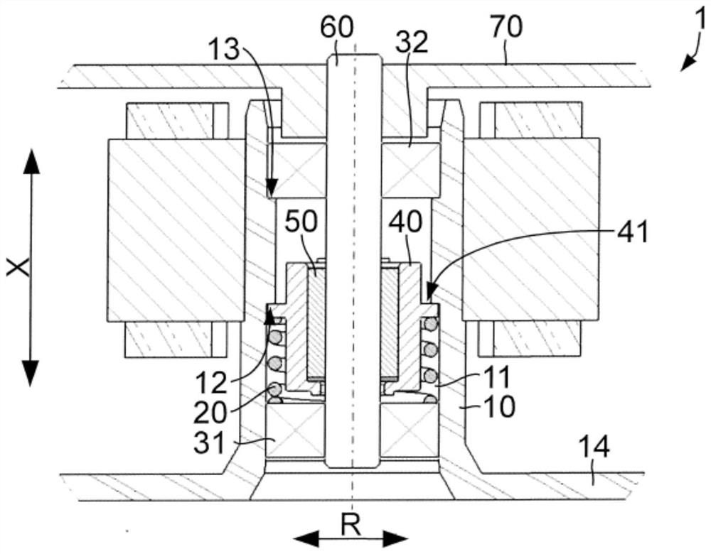
[0031] exist figure 1 , image 3 and Figure 4 In the shown locking device 1 for a ventilator (not shown), the rotor shaft 60 extends through the support tube 10 along the axis of rotation (shown in dotted lines). The rotor shaft 60 is mounted relative to the support tube 10 by means of a bearing arrangement consisting of a first bearing 31 and a second bearing 32 . The free-running sleeve 50 is slipped over a section of the rotor shaft 60 and is connected to the rotor shaft in a rotationally fixed manner, for example in a clamping manner. On its underside, the support tube 10 adjoins a flange 14 by means of which the locking device 1 can be fastened, for example, to a base plate or a housing. The rotor 70 is non-rotatably connected to the rotor shaft 60 on that side of the rotor shaft 60 facing away from...


PUM


Abstract

The invention relates to a locking device (1) for a fan, which is used for locking a direction of rotation of a rotor (70), by means of which rotor a fan wheel of the fan can be driven, The locking device includes a support tube (10), a rotor shaft (60) and an idler sleeve (50), wherein the idler sleeve (50) is accommodated in the support tube (10) and extends through The rotor shaft (60) of the idler sleeve (50) is anti-rotationally connected, and wherein the idler sleeve (50) connects the rotor shaft (60) at least in the direction of rotation of the rotor Rotational locking relative to said support tube (10).

Description

technical field [0001] The invention relates to a locking device for a fan for locking a direction of rotation of a rotor that can drive a fan wheel of the fan. Background technique [0002] Various motor-driven fans are known in the prior art. The motor or the output shaft of the motor connected to the rotor is connected to the fan wheel so that the fan wheel can be driven in rotation by means of the motor. The fan has at least one predetermined first direction of rotation in which the fan wheel is actively driven and an air flow is created. When flow is no longer required, the motor is switched off. However, an air flow opposite to the previously established flow may cause the blower wheel to passively rotate in a second, opposite direction of rotation, against the predetermined first direction of rotation. When the rotor rotates against the predetermined first direction of rotation, this results in the sensorless motor subsequently not starting or starting poorly. In ...

Claims


Application Information

Patent Timeline
Patent Type & Authority Patents(China)
IPC IPC(8): F04D25/02F04D29/056F16D13/00F16D41/02F04D25/06
CPCF04D25/022F04D29/056F04D25/0613F16D41/02F04D25/06F05D2260/40F05D2260/90
Inventor A·弗莱格G·朗格内克
Owner EBM PAPST ST GEORGEN & -
Why Eureka
Try Eureka