Cleaning device of die cutting machine cutter plate for packing case production

A technology for cleaning devices and packaging boxes, applied in the field of printing, can solve the problems of long cleaning time and complicated cleaning process.

Active Publication Date: 2020-10-20
武汉市建桥印务有限公司
View PDF10 Cites 0 Cited by
  • Summary
  • Abstract
  • Description
  • Claims
  • Application Information

AI Technical Summary

Problems solved by technology

[0004] The above-mentioned existing technical solutions have the following defects: when using the above-mentioned die-cutting machine, it is necessary to bond the die-cutting knife strip, the indentation strip and the sponge spring pad according to the product in the template frame to form the die-cutting knife bottom plate. When it is necessary to change the version, it is necessary to tear off the cutter strip, indentation strip and sponge spring pad on the bottom plate of the die-cutting knife, and then glue a new one in the template frame. However, the cutter strip, indentation strip and sponge spring pad After it comes down, there will be a lot of super glue left on the upper surface of the formwork frame. Generally, the staff needs to spray gasoline on the upper surface of the formwork frame, then remove it with a spatula, and then polish it with a roving cloth to make the surface smooth. Wipe the upper surface of the template frame with a rag. The whole cleaning process is complicated and takes a long time, so it needs to be improved

Method used


Image

  • Cleaning device of die cutting machine cutter plate for packing case production
  • Cleaning device of die cutting machine cutter plate for packing case production

Examples


Embodiment Construction

[0042] The present invention will be described in further detail below in conjunction with the accompanying drawings.

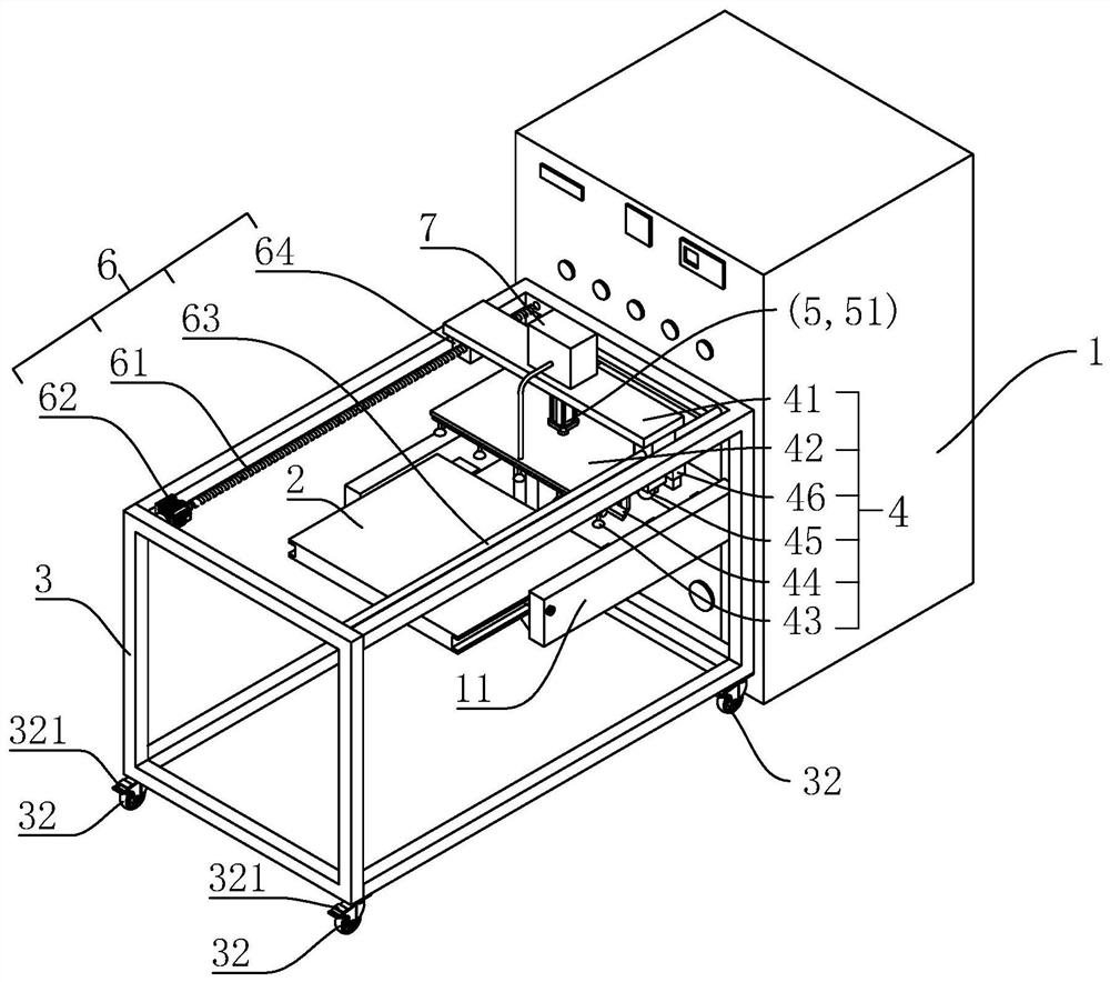
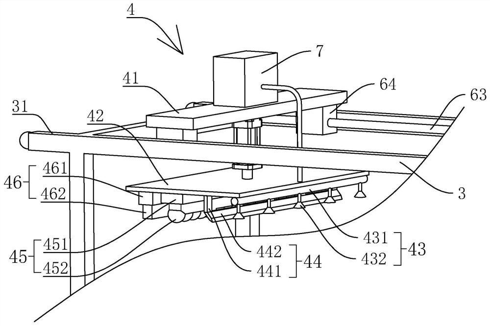
[0043] refer to figure 1 , is a cleaning device for a die-cutting machine knife plate for packaging box production disclosed by the present invention, comprising: a body 1, a die-cutting knife bottom plate 2, a moving frame 3, a cleaning assembly 4, a power part 5 and a driving assembly 6; the body 1 There is a bar-shaped opening along the horizontal direction, and the opposite sides of the bar-shaped opening in the length direction extend outwards and are welded with stainless steel chute plates 11, and the sides of the two chute plates 11 that are close to each other are provided with die cutters. The chute where the base plate 2 slides, the opposite sides of the die-cutter base plate 2 are slidably assembled between two chute plates 11, and the die-cutter base plate 2 can extend into the inside of the body 1 along the strip-shaped opening; the moving frame...


PUM


Abstract

The invention relates to a cleaning device of a die cutting machine cutter plate for packing case production. The cleaning device comprises a machine body, a die cutting cutter bottom plate, a movingframe, a cleaning assembly, a power part and a drive assembly. A strip-shaped opening is formed on the machine body in the horizontal direction, and the two opposite sides of the strip-shaped openingextend outwards to be provided with sliding groove plates. The two sides of the die cutting cutter bottom plate are assembled between the two sliding groove plates in a sliding manner, and the die cutting cutter bottom plate stretches into the machine body along the strip-shaped opening. The moving frame is separably assembled on the machine body, and the moving frame is located above the slidinggroove plates and covers the two sliding groove plates. The drive assembly is arranged on the moving frame. The cleaning assembly is arranged on the drive assembly. The drive assembly drives the cleaning assembly to move in the sliding direction of the die cutting cutter bottom plate. The power part is arranged at the top end of the cleaning assembly and drives the cleaning assembly to ascend anddescend and be in contact with the upper surface of the die cutting cutter bottom plate. The cleaning device has the effects that the cleaning process of the die cutting cutter bottom plate is simple,and the cleaning time is short.

Description

technical field [0001] The invention relates to the technical field of printing, in particular to a cleaning device for a die-cutting machine blade used in packaging box production. Background technique [0002] Die-cutting machine is also called beer machine, cutting machine, CNC punching machine, mainly used for die-cutting of corresponding non-metallic materials, self-adhesive, EVA, double-sided adhesive, electronics, mobile phone rubber pad, etc. broken), indentation and hot stamping operations, lamination, automatic waste discharge, die-cutting machine uses steel knife, metal mold, steel wire (or template carved from steel plate), exerts a certain pressure through the embossing plate, and prints or The cardboard is rolled and cut into certain shapes. It is an important equipment for post-press packaging processing and molding. [0003] A Chinese patent with the notification number CN207448667U discloses a die-cutting machine, including a frame, the frame includes an u...

Claims


Application Information

Patent Timeline
Patent Type & Authority Applications(China)
IPC IPC(8): B08B3/02B08B1/00B31B50/14
CPCB08B3/02B08B1/006B08B1/005B31B50/14
Inventor 潘惠康杨小兵吕华廖金平
Owner 武汉市建桥印务有限公司
Why Eureka
Try Eureka