Linearly driven flexible gripper with variable rigidity and variable rigidity control method thereof
A variable stiffness, wire-driven technology, applied in the direction of manipulators, manufacturing tools, chucks, etc., can solve the problems of difficult to grasp easily damaged and easily deformed objects, long design cycle, low profit added value, etc.
- Summary
- Abstract
- Description
- Claims
- Application Information
AI Technical Summary
Problems solved by technology
Method used
Image
Examples
specific Embodiment approach
[0017] The preferred embodiment of the variable stiffness wire-driven flexible gripper of the present invention is:
[0018] It includes a base, a plurality of flexible fingers and motors are installed on the edge of the base, a vacuum bag is set on the outside of each flexible finger, a vacuum pump is installed in the middle of the base, and the vacuum pump is connected to the vacuum bag ;
[0019] The flexible finger includes a flexible finger skeleton. The middle of the flexible finger skeleton is a sheet structure, and a row of T-shaped block structures is arranged on both sides. A round hole is arranged in the middle of the T-shaped block structure, and a tendon rope is passed through the round hole. , the upper end of the key rope is connected to the motor, and the lower end of the key rope is connected to the top of the flexible finger skeleton;
[0020] A flexible sheet is connected to the outer end of the T-shaped block structure.
[0021] One end of the flexible th...
specific Embodiment
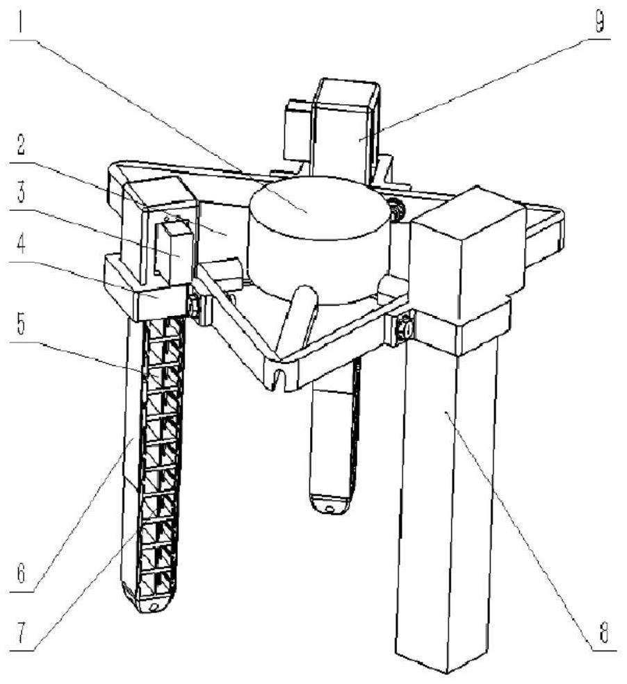
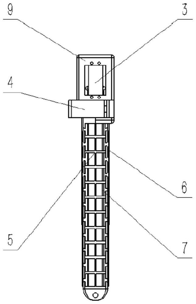
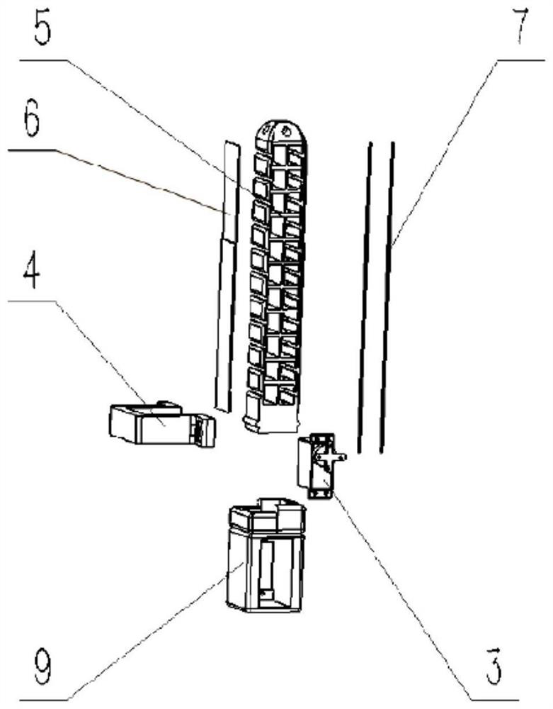
[0026] Such as figure 1 and figure 2 As shown, a soft gripper with variable stiffness by wire drive includes a vacuum pump 1, a base 2, a motor 3, a ferrule 4, a flexible finger frame 5, a flexible sheet 6, a tendon rope 7, a vacuum bag 8, and a motor box 9; The flexible finger skeleton 5 consists of a flexible thin-walled structure in the middle, and a series of T-shaped block structures on both sides. The top of the T-shaped block is also roughened. There are certain gaps between the T-shaped blocks. The thin-walled structure and the gap It is for the fingers to bend better. Simultaneously, there are some rows of round holes on the T-shaped block of the flexible finger frame 5 for the passage of the tendon cord 7. One end of the tendon cord links to each other with the top of the flexible finger frame 5, and the other end links to each other with the motor 3. Drives the flexion of the fingers. The motor 3 is located in the middle of the motor box 9, and the motor box 9 i...
PUM
 Abstract
Description
Claims
Application Information
 - R&D
- Intellectual Property
- Life Sciences
- Materials
- Tech Scout
- Unparalleled Data Quality
- Higher Quality Content
- 60% Fewer Hallucinations
Browse by: Latest US Patents, China's latest patents, Technical Efficacy Thesaurus, Application Domain, Technology Topic, Popular Technical Reports.
© 2025 PatSnap. All rights reserved.Legal|Privacy policy|Modern Slavery Act Transparency Statement|Sitemap|About US| Contact US: help@patsnap.com


