Fabricated building wall truss structure

A technology for building walls and truss structures, which is applied to truss structures, building components, building structures, etc., and can solve problems such as poor recycling rate of trusses, unoptimized support effects, and difficulty in changing internal support structures, etc.

Inactive Publication Date: 2020-10-20
胡丹萍
View PDF6 Cites 0 Cited by
  • Summary
  • Abstract
  • Description
  • Claims
  • Application Information

AI Technical Summary

Problems solved by technology

[0003] The lap joint of the truss is usually to connect the web and the upper and lower chords by welding to evenly distribute the load of the truss and improve the support strength of the truss, but the web and the chord are directly connected by welding. On the one hand, the transportation cost of this kind of integrated truss is high, and the recycling rate of the truss connected by welding is poor. At the same time, the adjustability of the integrated truss is poor. After welding, it is difficult to change its internal support structure. Lead to support effect can not achieve the best

Method used


Image

  • Fabricated building wall truss structure
  • Fabricated building wall truss structure
  • Fabricated building wall truss structure

Examples


Embodiment 1

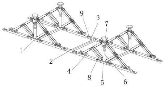
[0032] A prefabricated building wall truss structure, such as Figure 1-4As shown, it includes a triangular connection mechanism 1, and there are multiple groups of the triangular connection mechanism 1. A horizontal connecting plate 2 is arranged between two groups of horizontal triangular connecting mechanisms 1, and a horizontal connection plate 2 is arranged between two vertical groups of A longitudinal connecting plate 3 is arranged between them, and a plurality of installation blocks 9 are interspersed and connected to the upper end of the transverse connecting plate 2, and the transverse connecting plate 2 and the triangular connection mechanism 1 are clamped together by a plurality of installation blocks 9; The triangular connection mechanism 1 includes a support frame 4 and a connecting frame 5. There are two supporting frames 4, and a connecting frame 5 is arranged between the two supporting frames 4. The upper end of the connecting frame 5 is interspersed with a plur...

Embodiment 2

[0035] On the basis of Example 1, as Figure 5 As shown, a flower-shaped connecting groove 31 is opened at both ends of the longitudinal connecting plate 3, and one end of the longitudinal connecting plate 3 is sleeved in the slot 55 to engage with the flower-shaped connecting block 56 and the two connecting frames 5 are fixed by screws. Connection, the connection relationship between the longitudinal connecting plate 3, the transverse connecting plate 2 and the support frame 4 is the same as that of the connecting frame 5 and the supporting frame 4, and the connection relationship between the transverse connecting plate 2 and the longitudinal connecting plate 3 is the same as that between the connecting frame 5 and the longitudinal The connection relationship between the connecting plates 3 is the same, by making the structural design of the transverse connecting plate 2 the same as that of the connecting frame 5, and the installation method between the longitudinal connecting...

Embodiment 3

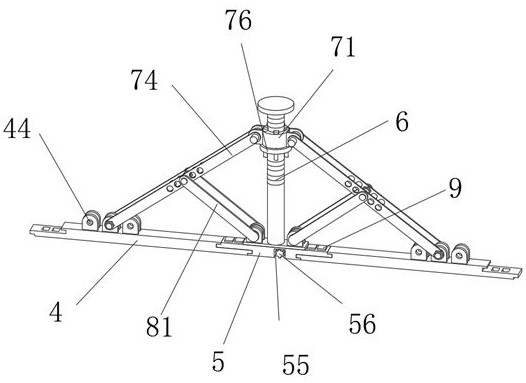
[0037] On the basis of Example 2, such as Figure 6 As shown, the bending mechanism 7 includes a sliding ring 71 and an adjusting ring 76. The upper end of the sliding ring 71 is interspersed with a plurality of limit rods 72. The limit rods 72 are distributed in a circular array around the center of the slide ring 71. The slide ring 71 Two connecting lugs 73 are uniformly formed on both sides of the outer surface of the outer surface, and the outer sides of the two connecting lugs 73 are connected with a curved rod 74 through the rotation of the rotating shaft. The middle part of the curved rod 74 has a plurality of connecting holes 75, an adjusting ring 76 and a sliding The diameters of the rings 71 are the same, and the upper end of the adjusting ring 76 is provided with a plurality of limit holes 77 that pass through up and down, and the limit holes 77 correspond to the positions of the limit rods 72; One end of the rod 74 away from the connecting ear 73 is fixedly connect...


PUM


Abstract

The invention discloses a fabricated building wall truss structure. The fabricated building wall truss structure comprises a plurality of groups of triangular connection mechanisms, wherein transverseconnection plates are correspondingly arranged between every two groups of transverse triangular connection mechanisms, longitudinal connection plates are correspondingly arranged between the two groups of longitudinal triangular connection mechanisms and the two longitudinal transverse connection plates, a plurality of installation clamping blocks are correspondingly connected to the upper endsof the transverse connection plates in a penetrating mode, and the transverse connection plates and the triangular connection mechanisms are clamped together through the multiple installation clampingblocks; and the triangular connection mechanisms comprise supporting frames and connecting frames, supporting columns are correspondingly and fixedly welded to the upper ends of the connecting frames, bending structures are correspondingly arranged on the upper parts of the supporting columns, the lower parts of the two sides of the bending mechanisms are correspondingly connected with the adjacent supporting frames, and web member mechanisms are arranged at the upper ends of the connecting frames and on the two sides of the supporting columns. According to the fabricated building wall trussstructure, assembly and splicing are convenient, the transportation cost is saved, reusing is achieved, adjusting is convenient, and the application range is wide.

Description

technical field [0001] The invention relates to the technical field of construction engineering, in particular to an assembled building wall truss structure. Background technique [0002] The truss is a structure composed of rods connected by hinges at both ends. The truss rods mainly bear axial tension or pressure, and make full use of the strength of the material. When the span is large, it can save materials and reduce its own weight compared with solid web beams. And increase the rigidity, the most common shape is straight line and triangle. [0003] The lap joint of the truss is usually to connect the web and the upper and lower chords by welding to evenly distribute the load of the truss and improve the support strength of the truss, but the web and the chord are directly connected by welding. On the one hand, the transportation cost of this kind of integrated truss is high, and the recycling rate of the truss connected by welding is poor. At the same time, the adjust...

Claims


Application Information

Patent Timeline
IPC IPC(8): E04C3/02E04B2/00
CPCE04B2/00E04C3/02
Inventor 胡丹萍
Owner 胡丹萍
Why Eureka
Try Eureka