An assembled laminated plate support device

A support device and a technology of laminated panels, which are applied in the preparation of pillars and building components on site, and construction, can solve problems such as poor support effect, damage to laminated panels, and inability to ensure pressure, so as to improve the connection support effect and slow down the movement. The effect of speed, good anti-slip effect

Active Publication Date: 2021-03-16
中嘉建盛建工集团有限公司
View PDF7 Cites 2 Cited by
  • Summary
  • Abstract
  • Description
  • Claims
  • Application Information

AI Technical Summary

Problems solved by technology

However, in the actual use of the above-mentioned patents, the pressure between the laminated board and the composite board is still not guaranteed. If the pressure is too large, it may cause damage to the laminated board. If the pressure is too small, the supporting effect will be poor, so there are certain limitations.

Method used


Image

  • An assembled laminated plate support device
  • An assembled laminated plate support device
  • An assembled laminated plate support device

Examples


Embodiment 1

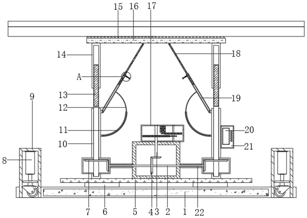
[0030] refer to Figure 1-5 , a prefabricated laminated plate support device, comprising a base 1, the four corners of the top outer wall of the base 1 are fixed with a pressure sensor 6 by screws, and the top of the pressure sensor 6 is fixedly installed with a mounting plate 5, and both sides of the top of the mounting plate 5 are welded There is a fixed tube 10, and the inner wall of the fixed tube 10 is connected with a threaded column 13 through bearing rotation, and the top of the threaded column 13 is connected with a threaded tube 14 through threads, and the top of the threaded tube 14 is fixed with the same support by bolts. Plate 16, the top outer wall of the support plate 16 is welded with protruding rods 15 distributed equidistantly, and the top outer wall of the protruding rods 15 is welded with claw-shaped convex strips 30 distributed equidistantly, to fix the opposite side of the tube tube 10 and the support plate 16 The storage tube 19 and the sliding rod 18 sl...

Embodiment 2

[0041] refer to figure 1 and Figure 4 , an assembly-type laminated plate support device, compared with Embodiment 1, this embodiment also includes a strengthening connecting pipe 22 welded to the opposite side of the square box and the transmission box, and the strengthening connecting pipe 22 is connected to the transmission rod 2 through the bearing Turn to connect.

[0042] When the present invention is in use, the setting of the reinforcing connecting pipe 22 can, on the one hand, play a good role in covering and protecting the transmission rod 2, and on the other hand, effectively strengthen the connection between the square box and the transmission box, so as to increase the structural strength of the device .


PUM


Abstract

The present invention belongs to the technical field of construction, in particular to an assembly-type laminated slab support device. Aiming at the problem that most traditional laminated slab support devices have relatively simple structures and are generally supported by steel columns, and the size of the support force at different positions varies greatly, the present invention proposes The following scheme includes a base, the four corners of the top outer wall of the base are fixed with pressure sensors by screws, and the top of the pressure sensor is fixedly installed with a mounting plate, and both sides of the top of the mounting plate are welded with fixed tubes, and the fixed tubes The inner walls of each are connected with threaded columns through bearing rotation. In the present invention, through the provided storage tube and sliding rod, after the adjustment of the supporting board is completed, the sliding rod can be squeezed and locked by rotating the screw thread against the bolt, thereby effectively improving the stability of the supporting board and ensuring the stability of the laminated board. Support effect; through the mutual cooperation between the set arc rod and the arc tube, it plays a good role in limiting the storage tube and improves the stability of the storage tube.

Description

technical field [0001] The invention relates to the technical field of construction, in particular to an assembled laminated plate support device. Background technique [0002] The laminated slab is an assembled integral slab formed by laminating prefabricated slabs and cast-in-place reinforced concrete layers. The laminated floor slab has good integrity, and the upper and lower surfaces of the slab are flat, which is convenient for decoration of the facing layer, and is suitable for high-rise buildings and large-bay buildings that require high overall rigidity. An integral part of laminated slabs is the cast-in-place concrete layer, the thickness of which varies according to the span size of the slab, but should be at least equal to the thickness of the prefabricated slabs. Laminated boards often need to use support devices when they are used. [0003] For example, the patent document with the Chinese patent application number CN2018222532108 relates to an assembled prefa...

Claims


Application Information

Patent Timeline
Patent Type & Authority Patents(China)
IPC IPC(8): E04G25/04E04G25/06
CPCE04G25/04E04G25/06
Inventor 刘增威邱童魏强李永黄浩
Owner 中嘉建盛建工集团有限公司
Why Eureka
Try Eureka