Antenna element and display device including same

An antenna device and electrode wire technology, which is applied to the antenna grounding device, antenna support/installation device, antenna, etc., can solve problems such as image degradation, user electrode identification, and image quality reduction without taking into account

Active Publication Date: 2020-10-20
DONGWOO FINE CHEM CO LTD
View PDF13 Cites 4 Cited by
  • Summary
  • Abstract
  • Description
  • Claims
  • Application Information

AI Technical Summary

Problems solved by technology

Thus, the image of the display device may be covered by the radiation electrode of the antenna, and the radiation electrode may be visually recognized by the user, thereby degrading the image quality.
[0005] In addition, in the case where the electrodes included in the antenna include multiple electrode wires, due to overlapping or misalignment of the electrode wires, it may cause the user's electrode recognition
[0006] For example, Korean Patent Application Publication No. 2013-0095451 discloses an antenna integrated in a display, but does not take into account the image degradation caused by the antenna in the display device

Method used


Image

  • Antenna element and display device including same
  • Antenna element and display device including same
  • Antenna element and display device including same

Examples


Embodiment 1

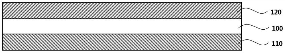
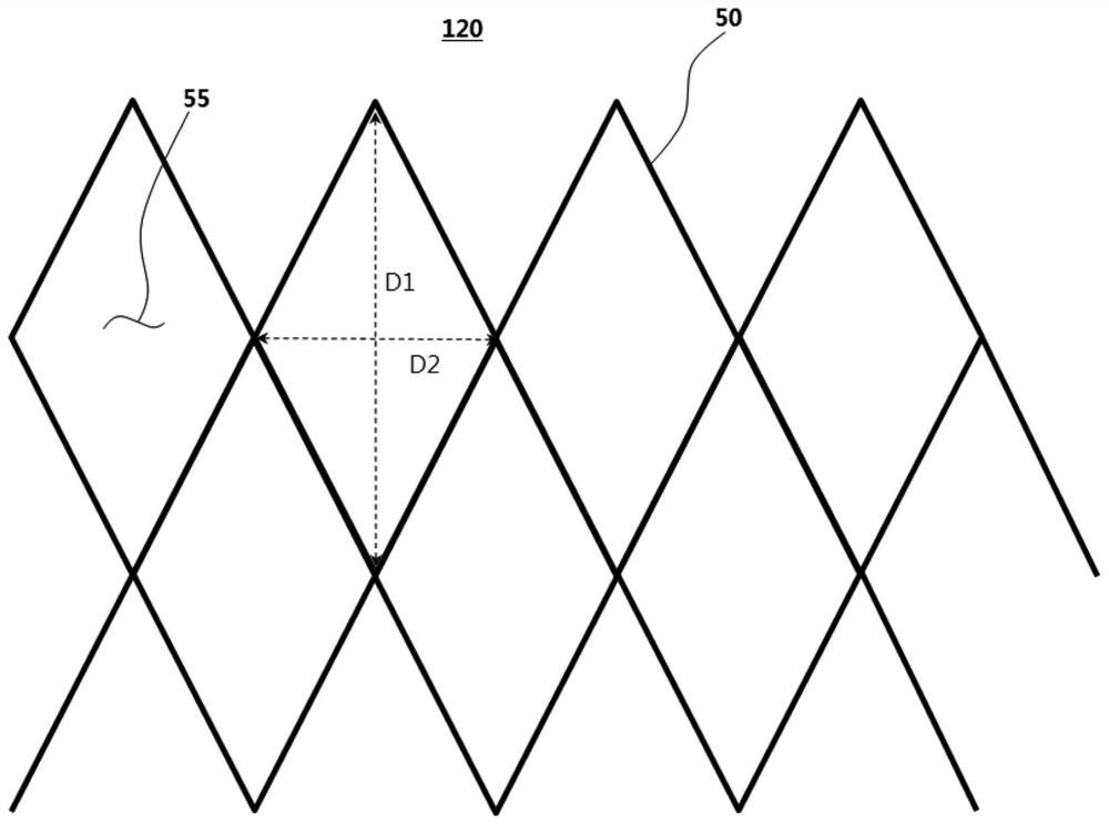
[0098] Alloy (APC) of silver (Ag), palladium (Pd) and copper (Cu) is used for the first electrode layer and the second electrode layer of the mesh structure arranged on the upper surface and the lower surface of the glass dielectric layer (0.7T). . In the grid structure, the electrode line width is 3 μm, and the electrode thickness (or height) is In the diamond-shaped cells contained in the first electrode layer and the second electrode layer, the length of the X-direction diagonal (short diagonal) is 200 μm, and the length of the Y-direction diagonal (long diagonal) is 400 μm. Such as Figure 5 As shown in , the above-mentioned first electrode layer and second electrode layer are arranged in such a manner that each unit cell is divided into four identical sub-cells.

Embodiment 2

[0100] In the diamond-shaped cells contained in the first electrode layer and the second electrode layer, the length of the X-direction diagonal (short diagonal) is 300 μm, and the length of the Y-direction diagonal (long diagonal) is 600 μm, except Otherwise, an antenna device was produced in the same manner as in Example 1.

experiment example

[0104] (1) Evaluation of Antenna Driving Characteristics

[0105] The antenna devices of the examples and the comparative examples were fed in such a manner that the above-mentioned first electrode layer was used as a radiation electrode and the above-mentioned second electrode layer was used as a ground electrode. Use a vector network analyzer (MS4644B, manufactured by Anritsu) and a radiation chamber to measure the antenna characteristics (S11, Re(Z), Im(Z), gain (Gain), directivity (Directivity), radiation efficiency (Radiation efficiency)) parameters. The results are shown in Table 1 below (*radiation efficiency (%)=(gain / directivity)*100).

[0106] [Table 1]

[0107]

[0108] Referring to Table 1, in the case where the above-mentioned grid structure is staggered as in Embodiment 1, the antenna characteristics are basically maintained without significant change or degradation.

[0109] (2) Evaluation of transmittance and electrode visibility

[0110] 1) Measurement ...


PUM

PropertyMeasurementUnit
lengthaaaaaaaaaa
lengthaaaaaaaaaa
lengthaaaaaaaaaa

Abstract

The invention provides an antenna element and a display device including the same. The antenna element according to embodiments of the present invention comprises: a dielectric layer; a first electrode layer placed on the top surface of the dielectric layer, including a radiation electrode, and having a first mesh structure; and a second electrode layer placed on the bottom surface of the dielectric layer and having a second mesh structure. The first mesh structure and the second mesh structure are aligned to be projected with offset from each other in the plane direction with the dielectric layer interposed therebetween. The antenna device can be inserted or mounted in front of the display device to improve signaling sensitivity and transmittance and minimize degradation of image qualityof the display device. In addition, the antenna device may include a mesh structure formed of a metal material to have improved flexibility, and thus may be effectively applied to a flexible display device.

Description

technical field [0001] The present invention relates to an antenna device and a display device including the same. More specifically, the present invention relates to an antenna device including an electrode pattern and a display device including the antenna device. Background technique [0002] With the development of information technology, wireless communication technologies such as Wi-Fi, Bluetooth, etc. are combined with display devices in the configuration of, for example, smartphones. In this case, the antenna can be combined with the display device to provide a communication function. [0003] With the rapid development of mobile communication technology, an antenna capable of high frequency or ultra high frequency communication is required in the display device. In addition, in recent years, thin-layer display devices having high transparency and resolution, such as transparent display devices and flexible display devices, have been developed, and antennas with im...

Claims


Application Information

Patent Timeline
Patent Type & Authority Applications(China)
IPC IPC(8): H01Q1/24H01Q1/38H01Q1/50G09F9/00
CPCH01Q1/38H01Q1/50H01Q1/24G09F9/00H01Q1/243H01Q1/364H01Q9/0407H01Q1/22H01Q1/36H01Q1/48
Inventor 柳汉燮朴东必吴伦锡
Owner DONGWOO FINE CHEM CO LTD
Why Eureka
Try Eureka