Linear motor and three-degree-of-freedom planar motion platform

A technology of linear motor and planar motion, applied in the direction of electric components, electrical components, electromechanical devices, etc., can solve problems such as low efficiency, complex structure, long design cycle and delivery cycle

Pending Publication Date: 2020-10-20
江苏集萃苏科思科技有限公司
View PDF0 Cites 0 Cited by
  • Summary
  • Abstract
  • Description
  • Claims
  • Application Information

AI Technical Summary

Problems solved by technology

[0005] ①The final moving part is connected to the base through various mechanisms, and the disturbance of each layer mechanism will be transmitted to the final moving part, resulting in poor positioning accuracy of the platform;
[00

Method used


Image

  • Linear motor and three-degree-of-freedom planar motion platform
  • Linear motor and three-degree-of-freedom planar motion platform
  • Linear motor and three-degree-of-freedom planar motion platform

Examples


Embodiment 1

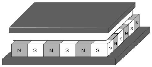
[0044] see Figure 11 and Figure 12 As shown, a linear motor, the linear motor includes a coil and a magnet, and the coil and the magnet are offset and positioned according to a certain offset distance D, so that the mover of the linear motor can be positioned relative to the linear The stator of the motor moves in a direction perpendicular to the driving direction of the linear motor.

Embodiment 2

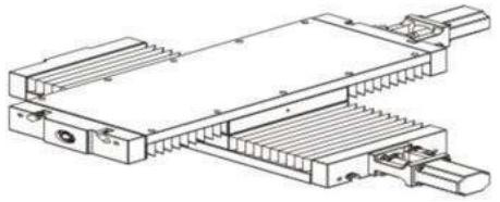
[0046] see Figure 4 , Figure 5 As shown, a three-degree-of-freedom planar motion table includes a relatively movable platform stator 1 and a platform mover 2, and four linear motors (see Embodiment 1) are arranged on the platform stator 1, respectively First, second, third and fourth linear motors 301, 302, 303, 304, the first and second linear motors 301, 302 are arranged oppositely, and the third and fourth linear motors 303, 304 are arranged oppositely , the platform mover 2 is located in the area formed by the first, second, third and fourth linear motors 301 , 302 , 303 , 304 .

[0047] Further, the magnet parts of the first, second, third and fourth linear motors 301, 302, 303, 304 are fixed on the platform stator 1, and the first, second, third and fourth The coils of the linear motors 301 , 302 , 303 , 304 are fixed on the platform mover 2 .

[0048] Further, an air bearing 4 is provided between the platform stator 1 and the platform mover 2 .

[0049] Further, t...

Embodiment 3

[0052] see Figure 6 , Figure 7 As shown, a three-degree-of-freedom planar motion table includes a relatively movable platform stator 1 and a platform mover 2, and four linear motors (see Embodiment 1) are arranged on the platform stator 1, respectively. 1. The second, third and fourth linear motors 301, 302, 303, 304, the first and second linear motors 301, 302 are arranged oppositely, and the third and fourth linear motors 303, 304 are arranged oppositely, The platform mover 2 is located in the area formed by the first, second, third and fourth linear motors 301 , 302 , 303 , 304 .

[0053] Further, the coil parts of the first, second, third and fourth linear motors 301, 302, 303, 304 are fixed on the platform stator 1, and the first, second, third and fourth The magnet parts of the linear motors 301 , 302 , 303 , 304 are fixed on the platform mover 2 .

[0054] Further, an air bearing 4 is provided between the platform stator 1 and the platform mover 2 .

[0055] Furth...


PUM


Abstract

The invention discloses a three-degree-of-freedom planar motion platform. The linear motor comprises a linear motor body, the linear motor body comprises a coil and a magnet, and offset positioning isconducted between the coil and the magnet according to a certain offset distance, so that a rotor of the linear motor body can move in the direction perpendicular to the driving direction of the linear motor body relative to a stator of the linear motor body; wherein the platform stator and the platform rotor can move relatively, the plurality of linear motors are arranged on the platform stator,magnet parts of the linear motors are fixed on the platform stator, and coil parts of the linear motors are fixed on the platform rotor; or, the coil part of the linear motor is fixed on the platformstator, and the magnet part of the linear motor is fixed on the platform rotor. The device is simple and compact in structure, high in layout efficiency, less in heating and high in positioning precision.

Description

technical field [0001] The invention belongs to the field of semiconductor equipment manufacturing and relates to a micro-operation motion table mechanism, in particular to a three-degree-of-freedom plane motion table. Background technique [0002] The existing three-degree-of-freedom planar motion table (moving straight in the X and Y directions, and rotating in the RZ direction) generally adopts two layout methods. One is to implement the three degrees of freedom movements with independent mechanisms and superimpose the three sets of mechanisms, such as figure 1 As shown, it is realized by superposition of multiple conventional linear motor mechanisms (linear motors are increasingly widely used in the field of linear transmission due to their high transmission efficiency compared with rotary motors), the structure of the conventional linear motor is as follows Figure 9 , 10 shown; Another layout is to use a customized planar motor to achieve three-degree-of-freedom moti...

Claims


Application Information

Patent Timeline
IPC IPC(8): H02K41/02
CPCH02K41/02
Inventor 罗岩陆海亮谢扬
Owner 江苏集萃苏科思科技有限公司
Why Eureka
Try Eureka