A Diesel Engine Cylinder Block Handling and Packing Equipment

A diesel engine and cylinder block technology, applied in the field of diesel engine cylinder block handling and packing equipment, to achieve the effect of ensuring structural strength and structural stability, ensuring accuracy and reliability, and wide operating area

Active Publication Date: 2020-08-21
Y & C ENGINE
View PDF8 Cites 0 Cited by
  • Summary
  • Abstract
  • Description
  • Claims
  • Application Information

AI Technical Summary

Problems solved by technology

[0005] The purpose of the present invention is to solve the disadvantages caused by lifting the cylinder block of the diesel engine by driving in the background technology

Method used


Image

  • A Diesel Engine Cylinder Block Handling and Packing Equipment
  • A Diesel Engine Cylinder Block Handling and Packing Equipment
  • A Diesel Engine Cylinder Block Handling and Packing Equipment

Examples


Embodiment 1

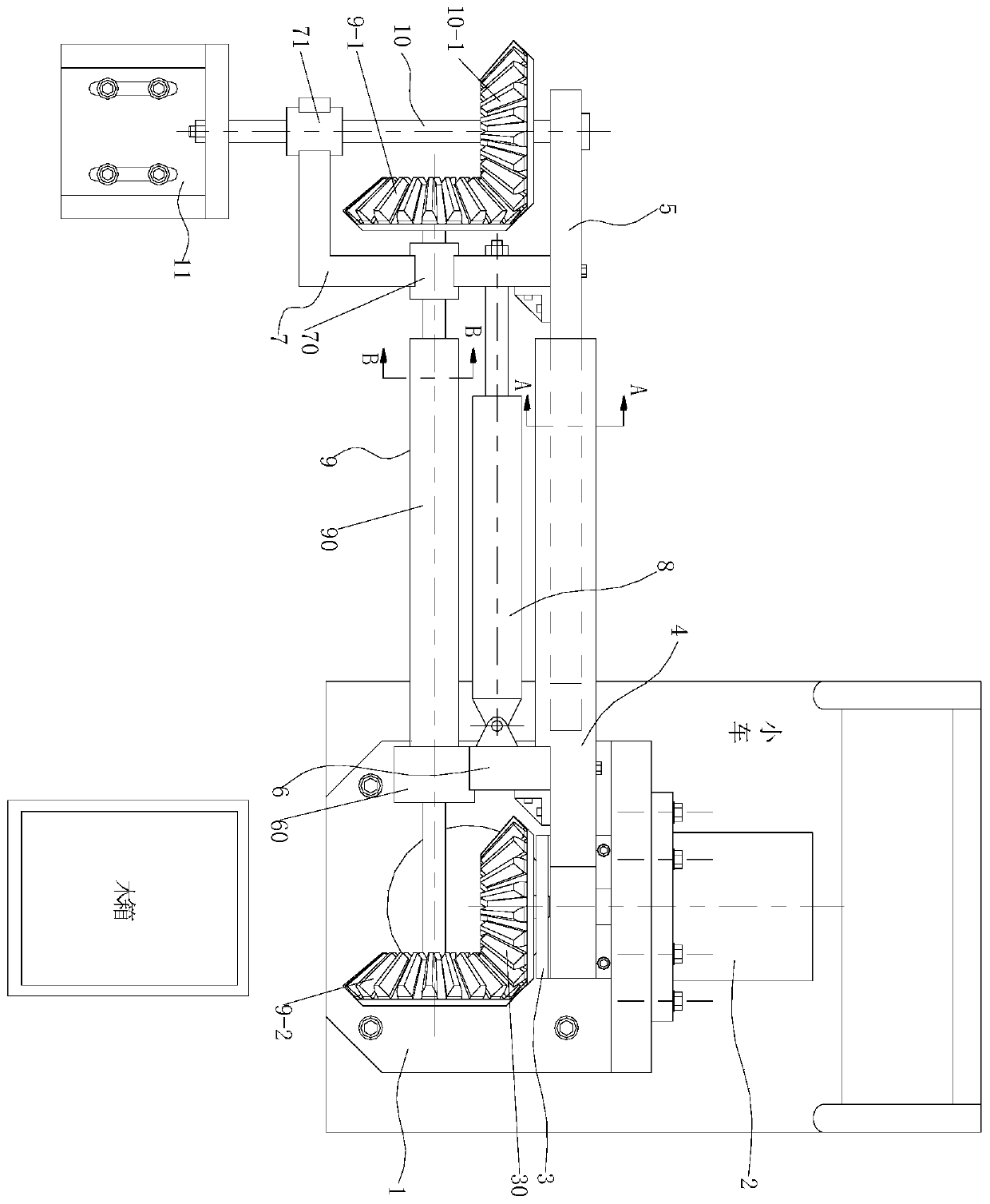
[0038] Refer to attached figure 1As shown, the trolley in this embodiment moves to the side of the diesel engine cylinder to be transported or boxed, and the electromagnet 11-1 and the diesel engine cylinder are in the same vertical plane position, and then the servo motor 2 is started, and the servo motor 2 The output shaft rotates forward or reversely to drive the rotary plate 4 to rotate forward or reverse synchronously around the axis of the output shaft of the servo motor 2, and then the rotary plate 4 carries the telescopic plate 5, the first axle frame 6, the second axle frame 7, and the telescopic rod 8. The telescopic shaft assembly 9, the rotating shaft 10 and the connecting frame 11 connected to the end of the rotating shaft 10 move together to a horizontal state. During this process, the bevel gear 2 9-2 is constrained to rotate by the fixed bevel gear 30, and then the bevel gear 2 9-2 rotates with the spline shaft 90, because the spline shaft 91 is axially sliding...

Embodiment 2

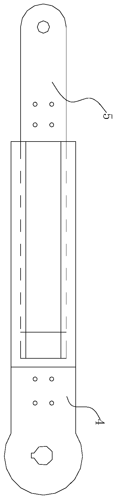
[0040] On the basis of Embodiment 1, the servo motor 2 drives the rotary plate 4 to rotate within an angle range of 180 degrees, so as to realize the adsorption and transportation of the diesel engine cylinders on both sides of the trolley; in addition, the telescopic rod 8 can pass through the axle frame 2 7 and the telescopic plate 5 Change the position of the rotating shaft 10 in the radial direction, so that the electromagnet 11-1 has a wide operating area and high flexibility. When the rotating plate 4 is in a horizontal state, it can absorb the far diesel engine cylinder; when the electromagnet 11-1 absorbs After the diesel engine cylinder is installed, the placement height can also be changed through the expansion and contraction of the telescopic rod 8, which has a wide range of applications; it can also be used to carry and place other large ferromagnetic workpieces, not limited to the diesel engine cylinder.

Embodiment 3

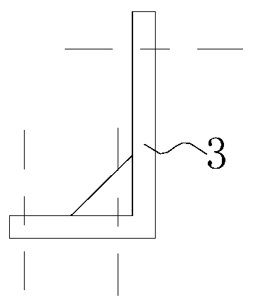
[0042] On the basis of Embodiment 1, the center of the small mounting seat 3 is fixed with a fixed bevel gear 30, and the central axis of the fixed bevel gear 30 is collinear with the axis of the output shaft of the servo motor 2, ensuring that the fixed bevel gear 30 In order to fix and constrain the gears and realize the planar movement of the connecting frame 11; the large mounting seat 1 is an "L"-shaped structure, and the small mounting seat 3 is an "L"-shaped structure, which ensures that the electromagnet 11-1 absorbs the workpiece structural strength and structural stability; the first shaft frame 6 is a "one"-shaped structure, and the second shaft frame 7 is an "L"-shaped structure, which realizes the parallel installation of the telescopic rod 8 and the telescopic shaft assembly 9, and ensures The support and rotation of the spline cylinder shaft 90 and the spline shaft 91 are improved, and the stability of the meshing of the first bevel gear 9-1 with the third bevel ...


PUM


Abstract

The invention discloses a diesel engine cylinder body carrying and boxing device, and belongs to the technical field of carrying tools. The diesel engine cylinder body carrying and boxing device comprises a large mounting base, a servo motor, a small mounting base, a rotating plate, a telescopic plate, a first shaft frame, a second shaft frame, a telescopic rod, a telescopic shaft assembly, a rotating shaft and a connecting frame; the servo motor is connected with the large mounting base, the small mounting base and the large mounting base are connected, the rotating plate and an output shaftof the servo motor share the coaxial line and are coaxially and rotatably connected, the telescopic plate is in sliding connection with the rotating plate, the end of the first shaft frame is in fastened connection with the rotating plate, one end of the telescopic rod is hinged to the first shaft frame, the other end of the telescopic rod is in fastened connection with the second shaft frame, thetelescopic shaft assembly is rotatably connected with the first shaft frame and the second shaft frame, the rotating s haft is rotatably connected with the end of the telescopic plate and a third shaft sleeve through bearings, and a third conical gear is fixedly arranged on the rotating shaft. The device is applied to carrying and boxing operation of a diesel engine cylinder, shaking and fallingcaused by lifting of the diesel engine cylinder by a crane for boxing are avoided, and accuracy and reliability of carrying and boxing are ensured.

Description

technical field [0001] The invention belongs to the technical field of handling tooling, and more specifically relates to a handling and packing equipment for diesel engine cylinder blocks. Background technique [0002] After the cylinder block of the diesel engine is processed, if it needs to be assembled directly, it can be used directly. If it needs to be stored in the warehouse, it needs to be packed in a wooden box, because there are many oil holes, lubricating oil pipelines, water outlets and cooling water pipes on the cylinder block of the diesel engine. Before storage, it needs to be bagged and sealed, and then sealed in a box to prevent dust from falling into the lubricating oil pipe or cooling water pipe of the cylinder block of the diesel engine, which will directly affect the life of the oil filter and other equipment in the future. [0003] The current operation of loading wooden boxes for diesel engine cylinders is: hang an electromagnet on the hook of the driv...

Claims


Application Information

Patent Timeline
Patent Type & Authority Patents(China)
IPC IPC(8): B65G47/92
CPCB65G47/92
Inventor 邹克胜梁和平王志新汪榆海薛立超陈凡凡
Owner Y & C ENGINE
Why Eureka
Try Eureka