Variable displacement rotary vane pump

A rotary vane pump, variable technology, applied in the field of oil pumps, can solve the problems of reducing pump efficiency and reliability

Active Publication Date: 2020-10-20
オーエムピーオフィチーネマゾッコパニョーニソチエタレスポンサビリタリミタータ
View PDF7 Cites 0 Cited by
  • Summary
  • Abstract
  • Description
  • Claims
  • Application Information

AI Technical Summary

Problems solved by technology

This reduces pump efficiency and reliability

Method used


Image

  • Variable displacement rotary vane pump
  • Variable displacement rotary vane pump
  • Variable displacement rotary vane pump

Examples


Embodiment Construction

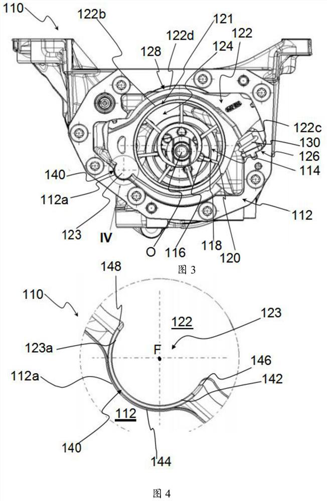
[0039] First refer to image 3 and Figure 4 , shows a first embodiment of a variable displacement rotary vane pump (in particular, a variable displacement oil pump) according to the present invention. The pump is indicated by numeral 110 .

[0040] The pump 110 includes a pump body 112 inside which a rotor 114 rotates. The rotor 114 is provided with radial cavities 116 in which vanes 118 slide. For clarity of illustration, reference numerals 116 and 118 are associated with only one of the radial cavities and one of the vanes shown.

[0041] The rotor 114 is rotatable about the axis of rotation O inside the pump body 112 .

[0042] The swing stator 122 is arranged in an eccentric position around the rotor 114 . The swing stator 122 is movable around a fulcrum 123 inside the pump body 112 .

[0043]The radially outer ends 120 of the blades 118 contact a ring 121 inserted between the rotor 114 and the oscillating stator 122 . The ring 121 is in contact with the radially i...


PUM


Abstract

The invention relates to a variable displacement rotary vane pump (110), comprising a pump body (112), a rotor (114) that rotates inside the pump body (112) around a rotation axis (0) and provided with a plurality of vanes (118), an oscillating stator (122) arranged in an eccentric position around the rotor (114), a fulcrum (123) for the rotation of said oscillating stator (122) with respect to the pump body (112), and adjusting means (126) for adjusting the displacement of the pump (110), the adjusting means (126) acting on the oscillating stator (122) to move it with respect to the rotor (114) and the pump body (112). The fulcrum (123) is integrally formed with said oscillating stator (122) and is housed in a recess (112a) formed in said pump body (112). The pump (110) comprises a sliding element (140) interposed between said fulcrum (123) and said recess (112a). Said sliding element (140, 240, 340) is at least partially free to rotate within said recess (112a).

Description

technical field [0001] The present invention relates to a variable displacement rotary vane pump. [0002] Preferably, the pump of the invention is used in the automotive field, in particular as an oil pump in an internal combustion engine of a motor vehicle. The pump according to the invention can also be used as a water pump in the engine cooling circuit of an internal combustion engine or as a fuel pump in the supply circuit of the aforementioned engine. Background technique [0003] In the following description, particular reference will be made to the use of the pump according to the invention as an oil pump in a gasoline or diesel internal combustion engine of a motor vehicle, it being understood that what is described more generally also applies to different types of internal combustion engines and other types of vehicles . [0004] figure 1 and figure 2 A prior art variable displacement oil pump is shown, generally designated by the reference numeral 10 . The p...

Claims


Application Information

Patent Timeline
IPC IPC(8): F04C2/344F04C14/22F04C15/00
CPCF04C2/344F04C14/22F04C14/226F04C15/0003F04C2240/10F04C2240/30F04C2240/50F04C2240/56
Inventor 朱塞佩·洛·毕尤多安吉洛·潘乔蒂
Owner オーエムピーオフィチーネマゾッコパニョーニソチエタレスポンサビリタリミタータ
Why Eureka
Try Eureka