Heat exchanger unit and air conditioner using same

A technology for air conditioners and heat exchangers, which is applied in the field of heat exchanger units and air conditioners, and can solve the problems of insufficient equalization of split flow, difference in split flow, and inability to split flow, etc.

Inactive Publication Date: 2020-10-20
PANASONIC INTELLECTUAL PROPERTY MANAGEMENT CO LTD
View PDF6 Cites 0 Cited by
  • Summary
  • Abstract
  • Description
  • Claims
  • Application Information

AI Technical Summary

Problems solved by technology

However, if the pressure loss of the outlet piping is different, the dryness of the inlet varies among the plurality of heat exchangers 101, resulting in a difference in the split flow rate, and the flow may not be evenly distributed to the plurality of heat exchangers.
That is, if the flow rate adjustment, in other words, pressure loss adjustment is performed by the flow rate adjustment unit 103 at the inlet of the heat exchanger, the equalization of the divided flow is improved compared with the case where the pressure loss adjustment is not performed, but the degree of equalization of the divided flow is not sufficient. , there is room for improvement

Method used


Image

  • Heat exchanger unit and air conditioner using same
  • Heat exchanger unit and air conditioner using same
  • Heat exchanger unit and air conditioner using same

Examples


Embodiment approach 1

[0050] [1-1. Structure]

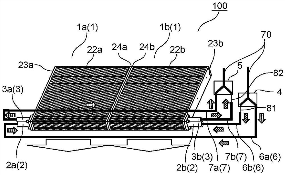
[0051] figure 1 It is a figure which shows the schematic structure of the heat exchanger unit concerning Embodiment 1 of this invention.

[0052] Such as figure 1 As shown, the heat exchanger unit 100 of this embodiment has a plurality of heat exchangers 1 (two heat exchangers 1a, 1b in this embodiment). Heat exchangers 1a, 1b are in figure 1 Set them side by side in the left-right direction (first direction).

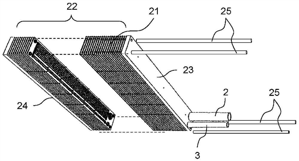
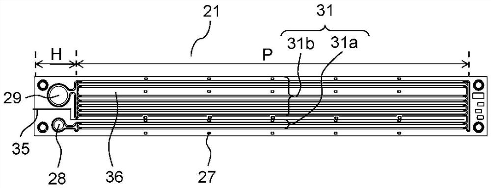
[0053] Each of the heat exchangers 1a, 1b includes, as described later: a first header flow path 28; a second header flow path 29 disposed downstream of the first header flow path; A plurality of refrigerant flow paths 31 ( image 3 reference).

[0054] Such as figure 1 As shown, each of the heat exchangers 1a, 1b has a first header flow path 28 ( image 3 Refer to) the inflow piping 6a, 6b. In addition, each of the heat exchangers 1a, 1b has a second header flow path 29 ( image 3 Refer to) outflow piping 7a, 7b. The inlet pipe...

Embodiment approach 2

[0108] Figure 7 It is a figure which shows the schematic structure of the heat exchanger unit concerning Embodiment 2 of this invention. Figure 8 is expressed in Figure 7 A diagram of the schematic structure of the part indicated by a in .

[0109] Such as Figure 7 As shown, in the heat exchanger unit 110 of this embodiment, branch pipes 9 are provided on the upstream side of the inlet pipes 2a, 2b of the heat exchangers 1a, 1b, and the refrigerant flowing into the heat exchanger unit 110 is transferred to heat. Structure of switches 1a, 1b branches. In addition, a throttle pipe 10 is provided on the inlet side (upstream side) of the branch pipe 9 .

[0110] The other configurations and the configurations of the heat exchangers 1a and 1b themselves are the same as those in Embodiment 1, and the same reference numerals are assigned to the same parts, and description thereof will be omitted.

[0111] Such as Figure 7 As shown, a branch pipe 9 is provided at a branchin...

Embodiment approach 3

[0116] [3-1. Structure]

[0117] Figure 9 It is a refrigeration cycle diagram of the air conditioner of this Embodiment 3.

[0118] The air conditioner 200 of this embodiment is comprised using any one of the heat exchanger units shown in Embodiment 1 and Embodiment 2. As shown in FIG.

[0119] Such as Figure 9 As shown, the air conditioner 200 includes an outdoor unit 51 and an indoor unit 52 connected to the outdoor unit 51 .

[0120] The outdoor unit 51 is provided with: a compressor 53 for compressing refrigerant; a four-way valve 54 for switching the refrigerant circuit according to cooling operation and heating operation; and an outdoor heat exchanger 55 for exchanging heat between the refrigerant and outside air. ; A pressure reducer 56 for decompressing the refrigerant; and an outdoor fan 59 .

[0121] In addition, the indoor unit 52 is provided with an indoor heat exchanger 57 and an indoor fan 58 for exchanging heat between the refrigerant and the indoor air. ...


PUM


Abstract

A heat exchanger unit (100) comprising a plurality of heat exchangers (1), each of the plurality of heat exchangers (1) having first piping (6) into which a refrigerant flows, a first header flow pathcommunicating with the outflow side of the first piping (6), a second header flow path arranged downstream from the first header flow path, a plurality of refrigerant flow paths enabling the first header flow path and the second header flow path to communicate with each other, and second piping (7) communicating with the outflow side of the second header flow path. In addition, the heat exchangerunit (100) comprises a first flow rate adjustment unit (81) provided to the first piping (6) of at least one of the plurality of heat exchangers (1), and a second flow rate adjustment unit (82) provided to the second piping (7) of at least one of the plurality of heat exchangers (1).

Description

technical field [0001] The present invention relates to a heat exchanger unit configured by connecting a plurality of heat exchangers in parallel, and an air conditioner using the same. In particular, it relates to a heat exchanger unit suitable when the heat exchanger is a plate-fin laminated heat exchanger, and an air conditioner using the same. Background technique [0002] Generally, an air conditioner circulates a refrigerant compressed by a compressor through heat exchangers such as a condenser and an evaporator, and exchanges heat with air to perform cooling or heating. In addition to the case where one heat exchanger is used alone, a plurality of heat exchangers may be combined to form a modularized heat exchanger unit. In such a case, it is preferable to make the refrigerant flow through each heat exchanger substantially uniformly so that the heat exchange efficiency of each heat exchanger is substantially the same. [0003] Therefore, in the conventional heat exc...

Claims


Application Information

Patent Timeline
Patent Type & Authority Applications(China)
IPC IPC(8): F25B41/00F24F1/0067F25B5/02F25B39/00F28F3/04
CPCF24F1/0067F28F9/26F28F3/04F28D2021/0068F28D1/0417F28D1/0325F25B41/48F25B41/45F25B39/028F25B39/04F25B13/00
Inventor 奥村拓也丸本一彦山本宪昭
Owner PANASONIC INTELLECTUAL PROPERTY MANAGEMENT CO LTD
Why Eureka
Try Eureka