Stone breaking machine used for hydraulic engineering building

A technology used in water conservancy projects and construction, applied in grain processing, etc., can solve the problems of manpower consumption, inability to realize automatic feeding of raw materials, and inconvenient crushing process, etc.

Inactive Publication Date: 2020-10-23
孙振梅
View PDF0 Cites 1 Cited by
  • Summary
  • Abstract
  • Description
  • Claims
  • Application Information

AI Technical Summary

Problems solved by technology

[0004] The purpose of the present invention is to solve the existing problems in the prior art that stone crushing machines often need to manually feed raw materials continuously during the stone crushing process, and cannot realize automatic feeding of raw materials. Therefore, extra manpower is required in the stone crushing process, and the entire stone crushing process Inconvenient disadvantages, and a kind of crushing machinery for water conservancy construction is proposed

Method used


Image

  • Stone breaking machine used for hydraulic engineering building
  • Stone breaking machine used for hydraulic engineering building
  • Stone breaking machine used for hydraulic engineering building

Examples


Embodiment 1

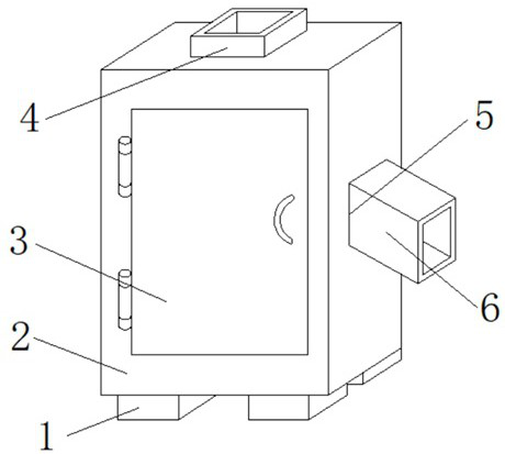
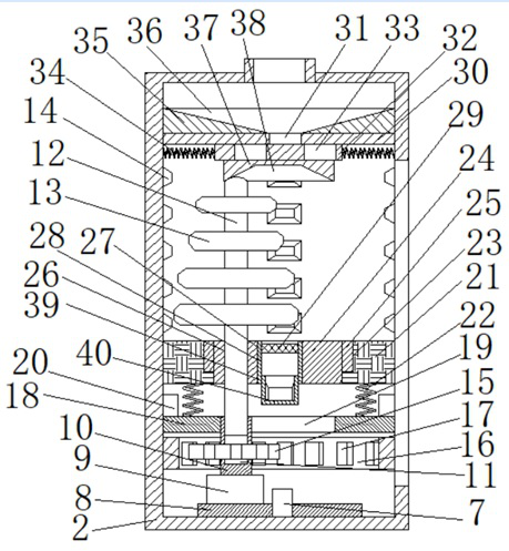
[0031] refer to Figure 1-7 , a stone crushing machine for water conservancy construction, comprising several bases 1, the tops of several bases 1 are jointly fixed with the same shell 2, the front side of the shell 2 is rotatably installed with a box door 3, and the top of the shell 2 is provided with Feed port 4, feed port 4 is used to put stone raw materials into the stone crushing machine, a first through hole 5 is opened on one side of the shell 2, and a discharge pipe 6 is fixedly installed in the first through hole 5, and the shell 2 A fixed rod 7 is fixedly installed on the inner wall of the bottom of the housing, and a turntable 8 is installed on the fixed rod 7. The fixed rod 7 is used as the rotation axis of the turntable 8, and the turntable 8 is rotatably installed on the bottom inner wall of the shell 2. Motor 9, the output shaft of motor 9 faces upwards, and the output shaft of motor 9 is fixedly installed with connecting seat 10, is provided with the first chut...

Embodiment 2

[0042] refer to Figure 1-7 , a stone crushing machine for water conservancy construction, including several bases 1, the tops of several bases 1 are jointly welded with the same shell 2, the front side of the shell 2 is rotatably installed with a box door 3, and the top of the shell 2 is provided with an inlet The feed port 4 and the feed port 4 are used to put stone raw materials into the stone crushing machine. A first through hole 5 is opened on one side of the shell 2, and a discharge pipe 6 is welded in the first through hole 5. The bottom of the shell 2 A fixed rod 7 is welded on the inner wall, and a turntable 8 is installed on the fixed rod 7. The fixed rod 7 is used as the rotation axis of the turntable 8. The turntable 8 is rotatably installed on the bottom inner wall of the shell 2. The top of the turntable 8 is fixed with a motor by screws. 9. The output shaft of the motor 9 faces upwards, and a connecting seat 10 is welded on the output shaft of the motor 9. The ...


PUM


Abstract

The invention belongs to the technical field of stone breaking machines and particularly relates to a stone breaking machine used for a hydraulic engineering building. Specific to the problems that inan existing stone breaking machine, raw materials frequently need to be input constantly by manual work in the stone breaking process, automatic input of the raw materials cannot be achieved, consequently, extra manpower needs to be consumed in the stone breaking process, and the whole stone breaking process is not convenient enough, the following scheme is put forwards. According to the scheme,the stone breaking machine comprises multiple bases, the tops of the multiple bases are commonly provided with the same shell, a fixing rod is installed on the inner wall of the bottom of the shell, and a rotary disc is installed on the fixing rod. A motor is installed on the top of the rotary disc, an output shaft of the motor is provided with a connecting seat, and a first sliding groove is formed in the connecting seat. A connecting rod is installed in the first sliding groove, and the top end of the connecting rod is sleeved with multiple cutter discs. According to the stone braking machine used for the hydraulic engineering building, the cutter discs can rotate on its axis and can also rotate, and therefore the stone breaking efficiency is improved; and meanwhile due to the structuressuch as a sliding plate, the stone breaking machine can conduct raw material supplementation automatically according to gravity changes.

Description

technical field [0001] The invention relates to the technical field of water conservancy engineering and stone crushing machinery, in particular to a stone crushing machinery for hydraulic engineering construction. Background technique [0002] In water conservancy projects, when building a building, a solid foundation is often required. In order to stabilize the foundation, it is often necessary to lay thick soil and gravel at the construction site. Therefore, it is often necessary to use a crushing machine to mechanically break large rocks. , so as to obtain relatively small stones for laying foundations. [0003] However, the existing stone crushing machines often need to manually put in raw materials during the stone crushing process, and cannot realize the automatic feeding of raw materials. A new type of crushing machinery is used to solve this problem. Contents of the invention [0004] The purpose of the present invention is to solve the existing problems in the ...

Claims


Application Information

Patent Timeline
Patent Type & Authority Applications(China)
IPC IPC(8): B02C18/10B02C18/16B02C18/24B02C23/16
CPCB02C18/10B02C18/16B02C18/24B02C23/16B02C2023/165
Inventor 孙振梅
Owner 孙振梅
Why Eureka
Try Eureka