A cylinder assembly machine

A technology of assembling machines and oil cylinders, which is applied in metal processing equipment, metal processing, manufacturing tools, etc., to achieve the effect of high safety guarantee, reasonable structure design, and avoidance of safety risks.

Active Publication Date: 2021-07-23
NINGBO JIALITE MACHINERY CO LTD
View PDF6 Cites 0 Cited by
  • Summary
  • Abstract
  • Description
  • Claims
  • Application Information

AI Technical Summary

Problems solved by technology

[0003] In view of the above-mentioned problems in the prior art, it is now intended to provide an oil cylinder assembly machine, which is provided with a main shaft and a clamping device on the upper part of the frame, through which the quick clamping of the oil cylinder can be realized, and It drives the clamped oil cylinder to rotate. At the same time, an operating platform is set on the lower part of the frame, and a deck for clamping the oil cylinder seat is set on the operating platform. The purpose of being installed on the cylinder seat avoids the problem of manual manipulation of wrenches and other tools to tighten the cylinder barrel. The operation is more convenient, the workload of the operator is reduced, and the assembly efficiency is improved. Moreover, there is a swing rod connected to the deck. , and the other end of the swing rod is provided with a spring and a trigger switch, so that after the cylinder barrel is tightened to a certain degree on the cylinder seat, the cylinder seat drives the deck to rotate, thereby making the swing rod compress or stretch the spring, and the trigger switch is activated , to realize the spindle reversal, so that the card seat can be reset, and it can prevent the structural damage such as slippery wire caused by excessive tightening of the cylinder barrel, improve the quality of the cylinder, and also ensure the tightening degree of the cylinder barrel of different cylinders on the cylinder seat The same, also improves the quality of the oil cylinder, avoids the safety risk caused by the judgment of the tightening degree only by manual experience, and the structural design is more reasonable

Method used


Image

  • A cylinder assembly machine
  • A cylinder assembly machine
  • A cylinder assembly machine

Examples


Embodiment Construction

[0034] In order to make the technical means, the creation characteristics, the purpose and efficacy of the present invention are readily understood, and the following examples are incorporated figure 1 Adherent Figure 8 The technical scheme provided by the present invention will be specifically described, but the following is not limited as the present invention.

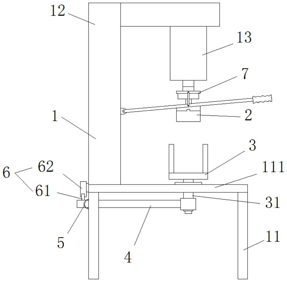
[0035] figure 1 A structural diagram of an embodiment of a cylinder assembly of the present invention. like figure 1 As shown, the cylinder assembly provided by the present embodiment includes: the frame 1, the spindle 13, the clamping device 2, the casing 3, the pendulum 4, the spring 5, the trigger switch 6, and the controller, the frame 1 is the spindle 13, The clamping device 2, the casing 3, the pendulor 4, the spring 5, the trigger switch 6, and the arrangement of the controller provide the mounting basis, and is rotated and rifleled by the spindle 13 and the clamping device 2. The cylinder holder is attached to ...


PUM


Abstract

The invention provides an oil cylinder assembly machine, which belongs to the technical field of oil cylinder assembly. An oil cylinder assembly machine includes a frame, a main shaft, a clamping device, a clamping seat, a swing rod, a spring and a controller; the invention realizes that the oil cylinder to be tightened is The clamping of the cylinder and the cylinder base realizes the tightening of the cylinder cylinder on the cylinder base, which is convenient to operate, with higher work efficiency and lighter work load. At the same time, there is a swing rod connected to the clamp, and the end of the swing rod is away from the clamp There is a spring and a trigger switch between it and the frame, so that after the cylinder barrel is tightened on the cylinder seat, the card seat can follow the rotation of the cylinder seat and drive the swing rod to swing, thereby triggering the trigger switch and controlling the spindle to reverse through the controller. Prevent structural damage such as slipping wires caused by over-tightening, make the tightening degree of different cylinders consistent, avoid the safety risk caused by the tightening degree of the cylinder being closely judged by manual experience, and improve the quality of the cylinder.

Description

Technical field [0001] The present invention relates to the technical field of cylinder assembly, and in particular, to a cylinder assembly machine. Background technique [0002] The cylinder includes at least a cylinder cartridge and a cylinder holder, and one end of the cylinder is fixed to the cylinder holder. Conventional, the cylinder cartridge and the cylinder block are assembled, and the cylinder barrel is rotated on the cylinder block, and then manually manually manually fix the cylinder holder, and clamp the cylinder cylinder through the wrench with the caliper. The cylinder cartridge is further tightened on the cylinder holder. However, in the process of tightening the cylinder holder in the cylinder holder, in the case of long assembly, the operator is frequently controlled, the operation is inconvenient, and the problem of working fatigue, affects the assembly efficiency, increasing the operator The work burden, additional, the above-described assembly process, the ti...

Claims


Application Information

Patent Timeline
Patent Type & Authority Patents(China)
IPC IPC(8): B23P19/04
CPCB23P19/006B23P19/04
Inventor 何立新俞雪根何斌俞凌峰
Owner NINGBO JIALITE MACHINERY CO LTD
Why Eureka
Try Eureka