Eureka AIR delivers breakthrough ideas for toughest innovation challenges, trusted by R&D personnel around the world.

Steadily floating workboat for hydraulic engineering

A technology for water conservancy projects and work boats, which is applied to special-purpose ships, ship construction, ship propulsion, etc. It can solve problems such as inability to work, poor applicability of work boats, and affecting work efficiency of water conservancy projects, so as to improve the level of safety protection, The effect of avoiding adverse effects

Active Publication Date: 2020-10-23
刘振华
View PDF7 Cites 2 Cited by
  • Summary
  • Abstract
  • Description
  • Claims
  • Application Information

AI Technical Summary

Problems solved by technology

[0009] Aiming at the deficiencies of the prior art, the present invention provides a stable floating operation boat for water conservancy projects, which solves the problem that the propeller at the bottom of the hull is easily affected by aquatic plants and algae at the bottom of the hull during the operation of the operation boat, causing the hull The propeller at the bottom is easily damaged and unable to work, forcing the staff to remove the aquatic plants and algae entangled on the propeller, which seriously affects the work efficiency of hydraulic engineering operations. Affects the normal operation of water conservancy projects, and the problem of poor applicability and low economic benefits of the workboat in the patent publication number CN105752304B scheme

Method used


Image

  • Steadily floating workboat for hydraulic engineering
  • Steadily floating workboat for hydraulic engineering
  • Steadily floating workboat for hydraulic engineering

Examples


Embodiment Construction

[0036]The following will clearly and completely describe the technical solutions in the embodiments of the present invention with reference to the accompanying drawings in the embodiments of the present invention. Obviously, the described embodiments are only some, not all, embodiments of the present invention. Based on the embodiments of the present invention, all other embodiments obtained by persons of ordinary skill in the art without making creative efforts belong to the protection scope of the present invention.

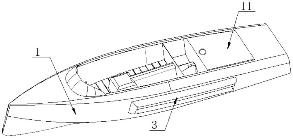
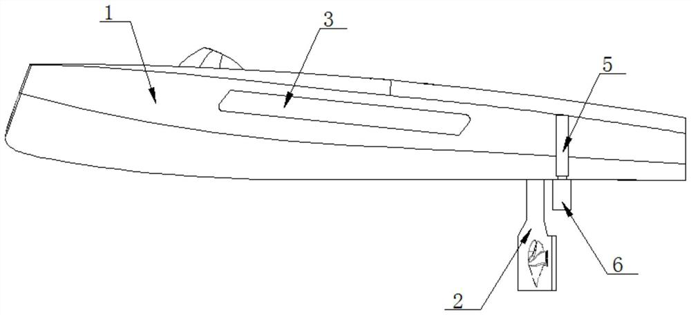
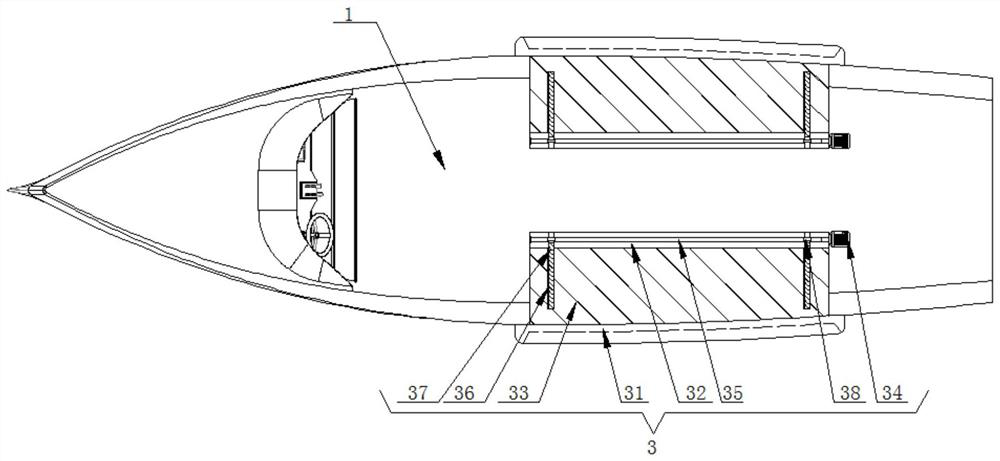
[0037] see Figure 1-3 , the embodiment of the present invention provides a technical solution: a stable floating workboat for water conservancy engineering, including a hull 1 and a drive box 2 located at the rear side of the bottom of the hull 1, the top of the drive box 2 is fixedly connected to the bottom of the hull 1 , the front and back of the hull 1 are provided with a floating mechanism 3, the floating mechanism 3 includes two floating blocks 31 symmet...


PUM


Abstract

The invention discloses a steadily floating workboat for hydraulic engineering, which comprises a boat body and a driving box positioned on the rear side of the bottom of the boat body, and relates tothe technical field of hydraulic engineering. The invention discloses a steadily floating workboat for hydraulic engineering. Two floating blocks on the two sides of the boat body are pushed to the two sides of the boat body through movable plates in the two floating mechanisms on the two sides of the boat body; the contact area between the boat body bottom surface and the water surface is increased; therefore, the effect of improving the floating stability of the boat body on the water surface is achieved; two first motor output shafts are used for rotating; the two speed reducing pieces arerotated out from the grooves; a first electric cylinder driving shaft in a movable column in the speed reducing piece extends out to push a movable rod in the movable column to extend out; tooth shapes of the bottom ends of the movable rods make contact with a mud layer at the water bottom, the bottom ends of the four movable rods are inserted into the mud layer at the water bottom, meanwhile, the floating mechanisms on the two sides of the boat body are unfolded, the stability of operation of the workboat on the water surface is effectively guaranteed, and the hydraulic engineering operationefficiency is improved.

Description

technical field [0001] The invention relates to the technical field of water conservancy engineering, in particular to a workboat capable of stably floating for water conservancy engineering. Background technique [0002] Operation ships are ships widely used in many fields such as port construction, waterway regulation, underwater construction, mineral mining, submarine umbilical laying, danger prevention and rescue, ocean development, ocean utilization, fishery production, etc. Water engineering operation ships refer to special Ships for various water operations, such as various drilling ships, piling ships, excavation and mining ships, carrying and unloading ships, crane ships, salvage ships, survey ships, pipe-laying ships, etc. [0003] In the prior art, there are the following defects in the process of using the workboat for water conservancy engineering: [0004] 1. During the working process of the workboat, the propeller at the bottom of the hull is easily affected...

Claims


Application Information

Patent Timeline
Patent Type & Authority Applications(China)
IPC IPC(8): B63B35/00B63B43/04B63H5/16B63B17/00B26D1/06
CPCB26D1/06B63B17/00B63B35/00B63B43/04B63H5/165
Inventor 刘振华李忠伟孙晓明李芳瑞于海梁崔晓燕王成华郑惠东贾宏星王最芳李晓琳张子杰张勇杨德宇张楠陈培元杨作鹏杨扬毕海英蒋海云王楠
Owner 刘振华
Why Eureka
Eureka Blog
Learn More