AI technical title is built by Patsnap AI team. It summarizes the technical point description of the patent document.
A pallet and tower crane technology, applied to cranes, etc., can solve problems such as no function and use value, inconsistent quality of whereabouts scheduling, safety accidents, etc.
Pending Publication Date: 2020-10-23
广西建工大都租赁有限公司
View PDF0 Cites 0 Cited by
Summary
Abstract
Description
Claims
Application Information
AI Technical Summary
This helps you quickly interpret patents by identifying the three key elements:
Problems solved by technology
Method used
Benefits of technology
Problems solved by technology
[0002] Tower crane is the most commonly used lifting equipment on construction sites. It is used to lift construction materials such as steel bars, wooden corrugations, concrete, and steel pipes. There is a lack of matching auxiliary tools in the lifting process, even if a few have tools. , is also a simple-structured material-holding tool, which can only be used to fix raw materials and has no special function and use value. During the lifting and landing process of raw materials, it is easy to appear uncontrollable links. Specifically, the falling distance of materials is a blind area. Due to the operation It is difficult for the personnel to quantitatively detect the falling distance and observe the falling position. They can only operate based on experience. Insufficient experience is likely to lead to inconsistent quality of falling scheduling, and even lead to some safety accidents, which directly affect construction efficiency and quality.
Method used
Image
Click on the blue label to locate the original text in one second.
Reading with bidirectional positioning of images and text.
Examples
specific Embodiment approach 1
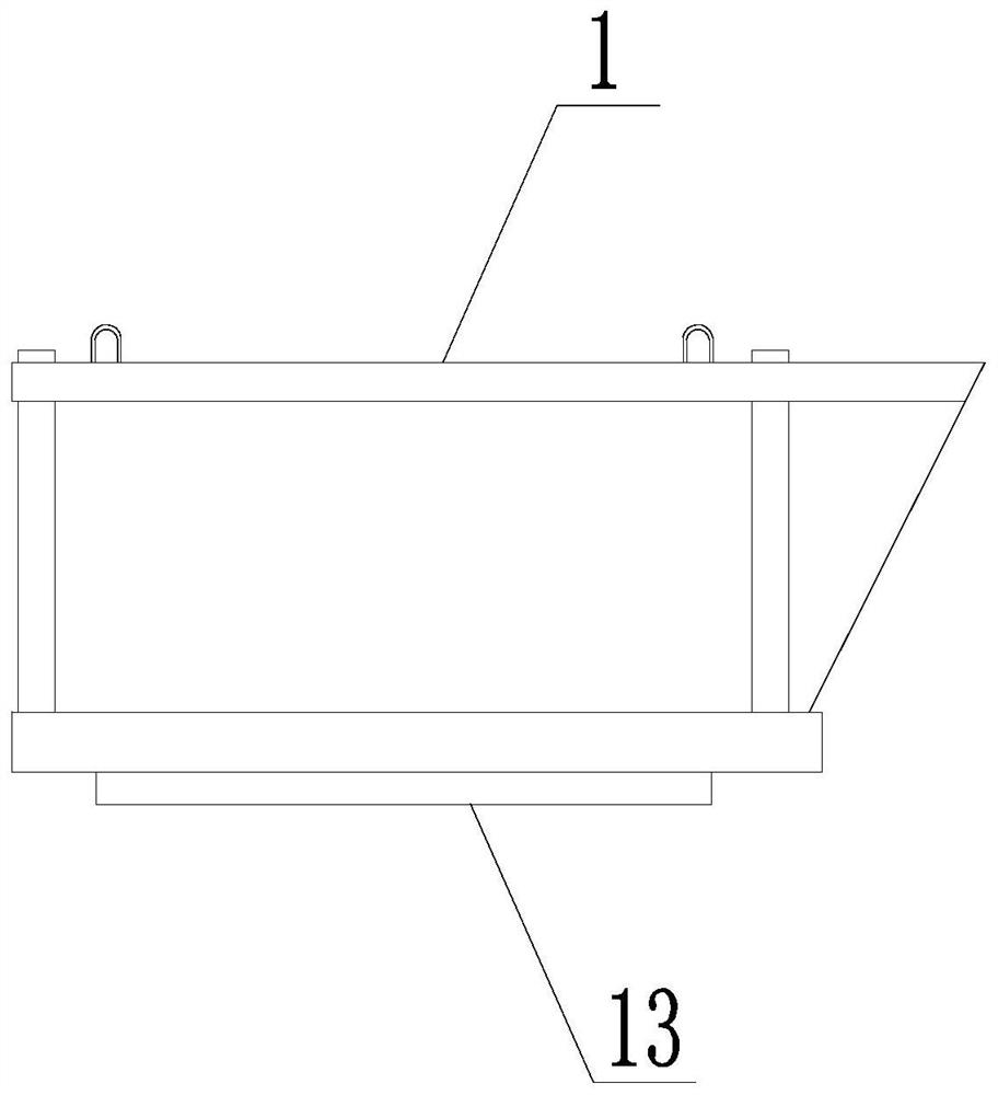
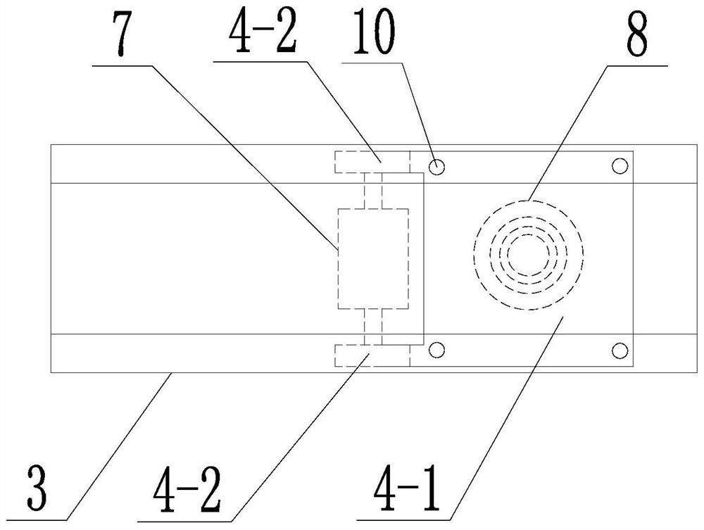
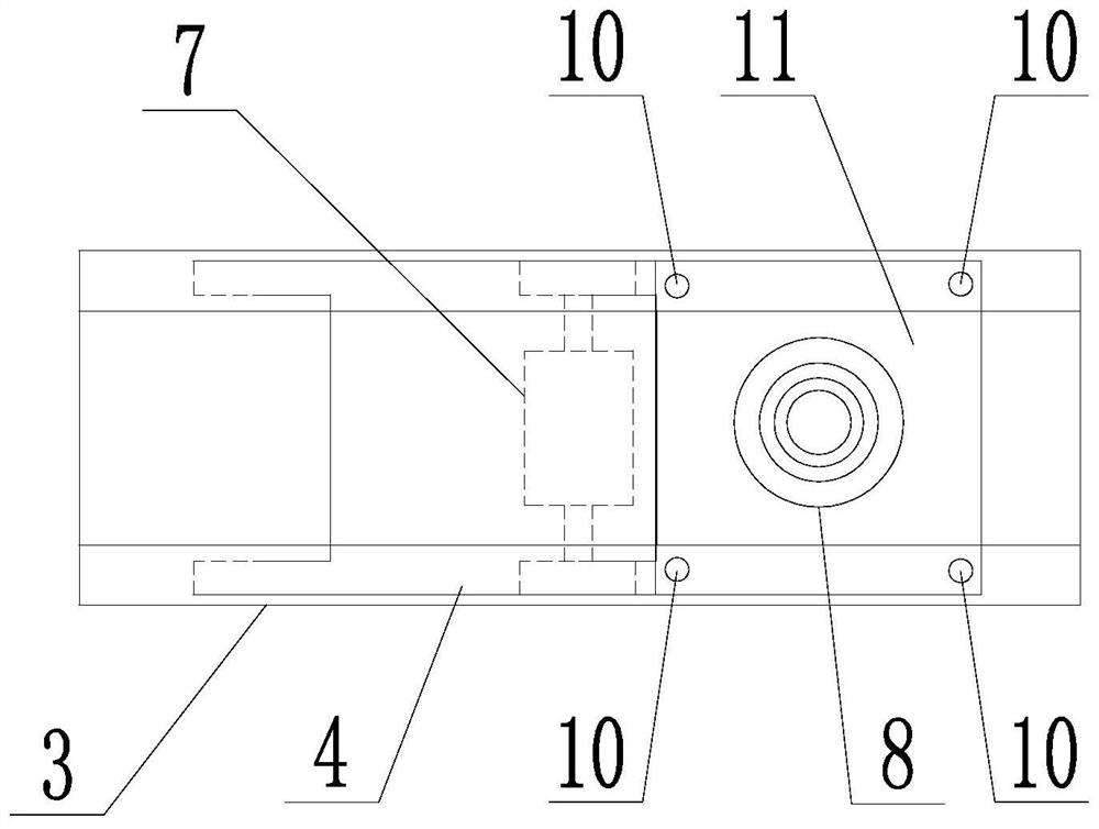
[0035] Specific implementation mode one: combine figure 1 , figure 2 , image 3 , Figure 4 , Figure 5 , Image 6 , Figure 9 and Figure 11 Describe this embodiment, this specific embodiment adopts the following technical solutions: this embodiment includes a tray body 1 and a monitoring assembly, and the monitoring assembly includes several monitoring units 2, and several monitoring units 2 are arranged on the tray body 1 Each monitoring unit 2 includes a housing 3, a first shield assembly, a camera 8, a controller 9 and a plurality of photosensitive sensors 10, the first shield assembly includes a cover plate 4, a rack 5, a gear 6 and a motor 7, The shell 3 is a box body and its bottom is processed with an opening 11 matching the first blocking assembly, the cover plate 4 is arranged at the opening 11, the motor 7 is fixedly installed in the shell 3, the output shaft of the motor 7 is sleeved with a gear 6, The upper end of the rack 5 meshes with the gear 6, the lo...
specific Embodiment approach 2
[0038] Embodiment 2: This embodiment is a further limitation of Embodiment 1, and the motor 7 is a biaxial motor.
[0039] In this embodiment, the motor 7 is an existing product.
[0040]In this embodiment, the motor 7 is preferably a small two-axis motor. Correspondingly, the motor 7 is correspondingly provided with two gears 6, and each gear 6 is correspondingly provided with two racks 5, and the two racks 5 are arranged on the cover plate 4 in parallel. both sides of the upper end.
specific Embodiment approach 3
[0041] Embodiment 3: This embodiment is a further limitation of Embodiment 1 or Embodiment 2. In this embodiment, the cover plate 4 is a rectangular plate.
[0042] In this embodiment, in order to save the weight of the cover plate 4 and facilitate operation, another structural form of the cover plate 4 is as follows:
[0043] The cover plate 4 includes a main board body 4-1 and two sub-board bodies 4-2, and the two sub-board bodies 4-2 are arranged side by side at one end of the main board body 4-1, and the two sub-board bodies 4-2 are strip-shaped As for the board body, each sub-board body 4-2 is correspondingly provided with a rack 5, and each sub-board body 4-2 is fixedly connected with its corresponding rack 5.
[0044] In this embodiment, the number of cover plates 4 is two, that is, the two first shielding components cooperate with each other to realize the operation process of quickly shielding or exposing the camera 8 .
PUM
Abstract
Provided is a monitoring tray for a tower crane. A tray used in cooperation with the tower crane can hardly carry out monitoring in the whole process, and consequently a dead zone is generated in thelifting process, and the rising and falling position is not accurate or safe. The monitoring tray comprises a tray body and a monitoring assembly. The monitoring assembly comprises a plurality of monitoring monomers, the monitoring monomers are arranged at the bottom of the tray body, and each monitoring monomer comprises a shell, a first shielding assembly, a camera, a controller and multiple photosensitive sensors. Each first shielding assembly comprises a cover plate, a gear rack, a gear and a motor. The cover plates are driven by the gear racks to do reciprocating motion in the length direction of the shells, the cameras are arranged in the shells, the camera shooting ends of the cameras faces openings, the multiple photosensitive sensors are all arranged on the outer walls of the shells and are arranged around the openings, and each photosensitive sensor is connected with the corresponding motor through the corresponding controller. The first shielding assemblies can be replaced with second shielding assemblies. The monitoring tray is used for the hoisting process.
Description
Technical field: [0001] The invention relates to a pallet, in particular to a monitoring pallet used for a tower crane. Background technique: [0002] Tower crane is the most commonly used lifting equipment on construction sites. It is used to lift construction materials such as steel bars, wooden corrugations, concrete, and steel pipes. There is a lack of matching auxiliary tools in the lifting process, even if a few have tools. , is also a simple-structured material-holding tool, which can only be used to fix raw materials and has no special function and use value. During the lifting and landing process of raw materials, it is easy to appear uncontrollable links. Specifically, the falling distance of materials is a blind area. Due to the operation It is difficult for personnel to quantitatively detect the falling distance and observe the falling position. They can only operate based on experience. Insufficient experience is prone to lead to inconsistent quality of whereabo...
Claims
Application Information
Patent Timeline
Application Date:The date an application was filed.
Publication Date:The date a patent or application was officially published.
First Publication Date:The earliest publication date of a patent with the same application number.
Issue Date:Publication date of the patent grant document.
PCT Entry Date:The Entry date of PCT National Phase.
Estimated Expiry Date:The statutory expiry date of a patent right according to the Patent Law, and it is the longest term of protection that the patent right can achieve without the termination of the patent right due to other reasons(Term extension factor has been taken into account ).
Invalid Date:Actual expiry date is based on effective date or publication date of legal transaction data of invalid patent.

