Drainage system for lowering anti-floating water level for prevention of up-floating

A drainage system and water level technology, which is applied in the direction of waterway system, drainage structures, sewage discharge, etc., can solve the problems affecting the normal use of underground buildings, damage to underground buildings, uplift and cracks in the bottom plate, etc.

Pending Publication Date: 2020-10-23
青岛时代建筑设计有限公司
View PDF0 Cites 0 Cited by
  • Summary
  • Abstract
  • Description
  • Claims
  • Application Information

AI Technical Summary

Problems solved by technology

[0002] With the development of the economy and the increase of urban population density, the development and application of underground space is becoming more and more extensive, especially in geological conditions with poor water permeability such as rocks, muddy soil, and clayey soil, and the anti-floating water level is relatively low. The high underground space structure, the anti-floating problem of this kind of building is becoming more and

Method used


Image

  • Drainage system for lowering anti-floating water level for prevention of up-floating
  • Drainage system for lowering anti-floating water level for prevention of up-floating

Examples


Embodiment 1

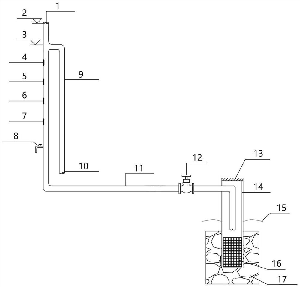
[0029] A drainage system for reducing the water level of the anti-floating installation The drainage system for reducing the water level of the anti-floating installation comprises a sump 17, the sump 17 is lower than the drainage level; the pressure-resistant chamber 14 is set as a closed tank, and the bottom is arranged It connects with the sump 17 in the sump 17, and the upper part extends out of the drainage plane; the diversion pipe 11, one end of the diversion pipe 11 extends into the pressure-resistant chamber 14, and the other end protrudes to a certain height higher than the drainage level; the drain valve 8, The drain valve 8 is arranged at the bottom of the diversion pipe 11, which is higher than the drainage plane; the water level observation hole is arranged on the diversion pipe 11; the pressure relief pipe 9, the pressure relief pipe 9 and the diversion pipe 11 are connected and arranged in parallel , the outlet is provided with a water diversion pipe 10 extendin...

Embodiment 2

[0031] A drainage system for reducing the water level of the anti-floating installation, which includes a sump 17, the sump 17 is lower than the drainage level; a pressure-resistant chamber 14, the pressure-resistant chamber 14 is set as a closed tank, and the bottom is arranged in the sump 17 and the sump 17 through, the upper part stretches out of the drainage plane; the diversion pipe 11, one end of the diversion pipe 11 extends into the pressure chamber 14, and the other end protrudes, and is higher than the drainage level by a certain height; the drain valve 8, the drain valve 8 is arranged on the diversion tube The bottom of 11 is higher than the drainage level; the water level observation hole is arranged on the diversion pipe 11; the pressure relief pipe 9, the pressure relief pipe 9 and the diversion pipe 11 are connected and arranged in parallel, and the outlet is provided with the diversion pipe 10 to extend to Drainage ditch; exhaust pipe 1, the upper end of the gui...


PUM


Abstract

The invention relates to a dewatering and drainage system, in particular to the dewatering and drainage system for underground construction. The purpose is to provide the dewatering and drainage system that can drain water above the drainage level, and can automatically drain water when the water is higher than the warning water level. The system comprises a water collection tank, a pressure-resistant bin, a honeycomb duct, a drain valve, a water level observation hole, a decompression pipe and an exhaust pipe, wherein the water collection tank is lower than a drainage plane; the pressure-resistant bin is arranged as a closed tank, the bottom part is arranged in the water collection tank to be communicated with the water collection tank, and the upper part extends out of the drainage plane; one end of the honeycomb duct extends into the pressure-resistant bin, and the other end extends out of the drainage plane and is a certain height higher than the drainage plane; the drain valve isarranged at the bottom of the honeycomb duct, and higher than the drainage plane; the water level observation hole is formed in the honeycomb duct; the decompression pipe and the honeycomb duct are communicated and arranged in parallel, and an outlet extends to a drainage ditch; and the exhaust pipe is arranged at the upper end of the honeycomb duct. The dewatering and drainage system is simple instructure, solves major problems, fundamentally solves the drainage problem of underground buildings such as basements and underground garages when the water level rises, and avoids the situation that the basements and the underground garages are flooded, and only water pumping can solve the problem.

Description

technical field [0001] The invention relates to a drainage system for lowering the anti-floating water level, in particular to a drainage system for lowering the anti-floating water level for underground buildings. Background technique [0002] With the development of the economy and the increase of urban population density, the development and application of underground space is becoming more and more extensive, especially in geological conditions with poor water permeability such as rocks, muddy soil, and clayey soil, and the anti-floating water level is relatively low. The high underground space structure, the anti-floating problem of this kind of building is becoming more and more prominent, and affected by the wet season, as well as the short-term heavy precipitation, the groundwater level rises, and the drainage is not timely during the construction process, resulting in the raft foundation in the water. Floating under the action of buoyancy, uplifts and cracks appear ...

Claims


Application Information

Patent Timeline
IPC IPC(8): E03F1/00E03F5/00E03F5/10B01D29/01
CPCB01D29/01E03F1/00E03F5/00E03F5/10
Inventor 付强李晓敏孙梦囡
Owner 青岛时代建筑设计有限公司
Why Eureka
Try Eureka