
High-pressure rotary piston impeller steam power machine

A technology of rotating piston impeller and steam power engine, applied in the field of rotating machinery, can solve the problems of low efficiency of heat engine, high energy consumption, inability to achieve strong thrust of train steam engine, etc.

Pending Publication Date: 2020-10-23
李海鹏
View PDF0 Cites 0 Cited by
  • Summary
  • Abstract
  • Description
  • Claims
  • Application Information

AI Technical Summary

Problems solved by technology

[0002] The steam engine uses steam as the working medium, and uses the steam to expand in the cylinder to push the piston to do work. The efficiency of the heat engine is very low, and it is a waste of energy to discharge the steam with high heat energy, while the steam turbine uses the steam to expand in the turbine to push the turbine to do work. , when the steam turbine is stopped and restarted, it is necessary to provide high-temperature and high-pressure steam again to heat the water into high-temperature steam. Every time it is started, it needs external assistance, and it cannot achieve the strong thrust of the train steam engine. Repeating this process consumes a lot of energy. Big

Method used


Image

  • High-pressure rotary piston impeller steam power machine
  • High-pressure rotary piston impeller steam power machine
  • High-pressure rotary piston impeller steam power machine

Examples


Embodiment Construction

[0022] In order to make the technical problems, technical solutions and beneficial effects to be solved by the present invention clearer, the present invention will be further described in detail in combination with the embodiments and accompanying drawings. It should be understood that the specific embodiments described here are only used to explain the present invention, not to limit the present invention. The technical solutions of the present invention will be described in detail below in conjunction with the embodiments and accompanying drawings, but the scope of protection is not limited thereto.

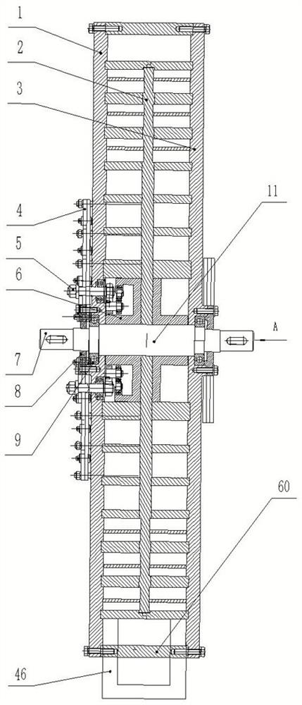
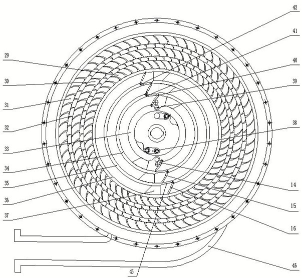
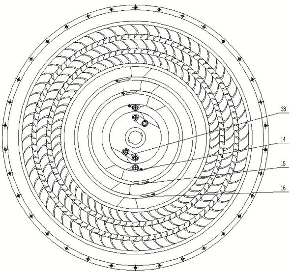
[0023] Such as figure 1 , figure 2 , image 3 As shown, it is a high-pressure rotary piston impeller steam power machine, including a left cylinder and a right cylinder. The left cylinder and the right cylinder share a casing 2 and are symmetrically distributed. The left bottom plate 1 and the casing 2 are sealed and connected to form the left cylinder and the right bottom ...


PUM


Abstract

The invention provides a high-pressure rotary piston impeller steam power machine and belongs to the field of rotary machines for converting heat energy of high-pressure steam into mechanical energy.Through the steam power machine, the problem of how to fully utilize high-temperature high-pressure steam to improve the heat engine efficiency of the steam power machine is solved. The steam power machine specifically comprises a steam cylinder, wherein the steam cylinder comprises a shell, a bottom plate and multiple annular partition plates arranged on the bottom plate, the partition plates arearranged concentrically from inside to outside, a spindle is arranged on the bottom plate and located at the center of the partition plates, the shell is movably connected with the partition plates through the spindle, a steam inlet is arranged at the inner side of the innermost partition plate, and a steam supply mechanism is connected with the steam inlet; a steam valve is arranged on each partition plate, a baffle is arranged at each steam valve, and the baffles are connected with a rebounding linkage mechanism, which is used for opening or closing the baffles simultaneously; and pistons corresponding to all annular tracks in position are fixedly connected to the inner side face of the shell, and the pistons are location in the annular tracks. Through the steam power machine, full utilization of the steam is realized, the heat engine efficiency is improved, and output power is increased.

Description

technical field [0001] The invention relates to a rotary machine which converts heat energy of high-pressure steam into mechanical energy, in particular to an elegant rotary piston impeller steam power machine. Background technique [0002] The steam engine uses steam as the working medium, and uses the steam to expand in the cylinder to push the piston to do work. The efficiency of the heat engine is very low, and it is a waste of energy to discharge the steam with high heat energy, while the steam turbine uses the steam to expand in the turbine to push the turbine to do work. , when the steam turbine is stopped and restarted, it is necessary to provide high-temperature and high-pressure steam again to heat the water into high-temperature steam. Every time it is started, it needs external assistance, and it cannot achieve the strong thrust of the train steam engine. Repeating this process consumes a lot of energy. big. Contents of the invention [0003] The invention ove...

Claims


Application Information

Patent Timeline
IPC IPC(8): F01B21/04F01B31/26
CPCF01B21/04F01B31/26
Inventor 李四良李海鹏李海燕
Owner 李海鹏
Learn More