
Pressing block of linear guide shaft

A technology of linear guide and compression block, which is applied in the direction of linear motion bearings, rigid supports of bearing components, bearings, etc., and can solve the problems of surface roughness of the outer diameter of easily damaged linear bearings, excessive energy consumption, and increased inner diameter clearance.

Pending Publication Date: 2020-10-23
JIASHAN CSB PLASTIC BEARING TECH CO LTD
View PDF0 Cites 0 Cited by
  • Summary
  • Abstract
  • Description
  • Claims
  • Application Information

AI Technical Summary

Problems solved by technology

However, in actual matching, the inner diameter of the bearing is the upper tolerance, and the outer diameter of the linear bearing is the lower tolerance. When the two are matched, sometimes they are too loose, and the gap is too large, which will affect the performance accuracy during use.
The inner diameter of the bearing is the lower tolerance, and the linear bearing is the upper tolerance. When the two are matched tightly, there is no gap. In use, not only consumes excessive energy, but also easily damages the surface roughness of the outer diameter of the linear bearing, which also affects its performance.
At the same time, even if the precision of the linear bearing and the bearing housing is high, after a period of use, the wear between the original linear bearing and the bearing will increase the inner diameter gap between the shaft and the bearing, resulting in vibration, noise and even vibration during the movement. The straight line accuracy cannot be guaranteed, which shortens the service life and affects the operating life of other parts of the whole machine

Method used


Image

  • Pressing block of linear guide shaft
  • Pressing block of linear guide shaft
  • Pressing block of linear guide shaft

Examples


Embodiment Construction

[0018] Specific embodiments of the present invention will be further described in detail below. It should be understood that the description of the embodiments of the present invention here is not intended to limit the protection scope of the present invention.

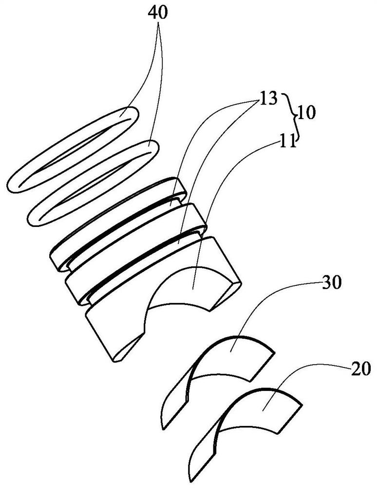
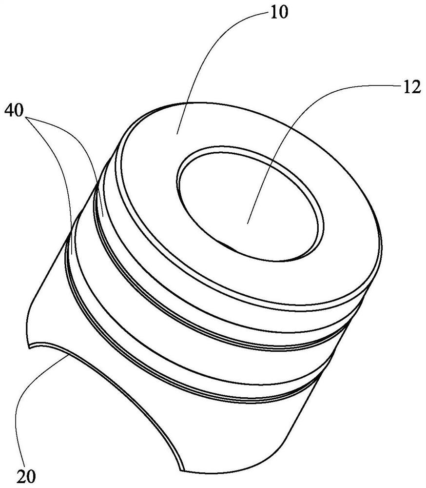
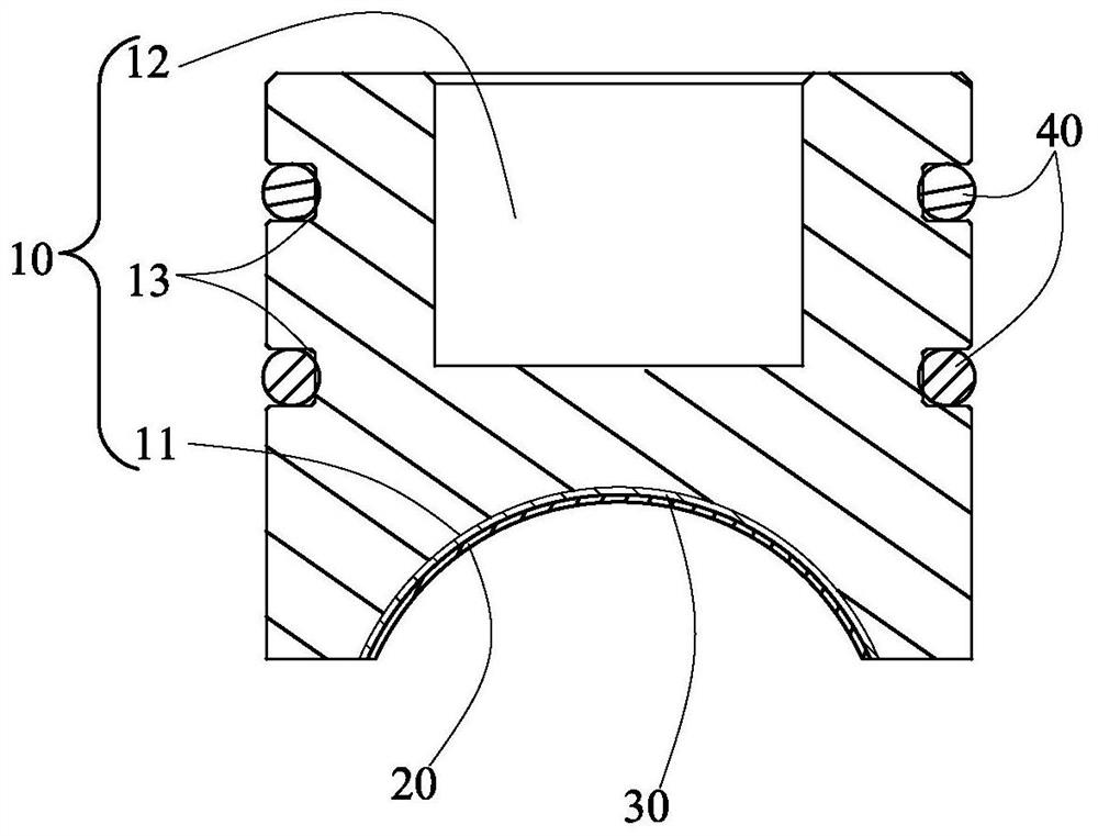
[0019] like Figure 1 to Figure 3 As shown, it is a structural schematic diagram of the compression block of the linear guide shaft provided by the present invention. The compression block of the linear guide shaft includes a body 10, a wear-resistant layer 20 arranged on the body 10, and a layer of glue for bonding between the body 10 and the wear-resistant layer 20. Layer 30, and at least one elastic ring 40 disposed on said body 10. It is conceivable that the pressing block of the linear guide shaft is assembled in an installation housing, and the installation housing is also provided with a matching seat hole for accommodating the body 10, which is not in the figure 1 Not shown, but it should be the prior art, ...


PUM

PropertyMeasurementUnit
Peel strengthaaaaaaaaaa
Compressive strengthaaaaaaaaaa
Shore hardnessaaaaaaaaaa

Abstract

The invention discloses a pressing block of a linear guide shaft. The pressing block of the linear guide shaft comprises a body, a wear-resisting layer and an elastic ring; the body comprises a pressing arc face, a spring containing hole and an elastic ring containing groove; the central axis of the pressing arc face is perpendicular to the central axis of the body, and the central axis of the pressing arc face intersects with the central axis of the body; the arch height of an arc where the contour line of the pressing arc surface is located is smaller than the diameter of the arc; the central axis of the spring containing hole coincides with the central axis of the body; and the wear-resisting layer is pasted to the pressing arc face, the elastic ring is contained in the elastic ring containing groove, and part of the elastic ring is exposed out of the elastic ring containing groove. According to the pressing block of the linear guide shaft, the loss of the contact surface caused byfriction between the wear-resisting layer and the shaft can be compensated in time, so that the pressing block can be tightly propped against the pressing arc surface of a matching shaft all the time,and the purpose of eliminating a gap is achieved.

Description

technical field [0001] The invention relates to the technical field of bearings, in particular to a pressing block of a linear guide shaft. Background technique [0002] In the matching application of ordinary linear bearing finished products, the product is first assembled into the matching bearing seat sleeve for fixing and positioning. After the inner diameter of the bearing is matched with the outer diameter of the bearing, the straight line operation is carried out. However, in actual matching, the inner diameter of the bearing is the upper tolerance, and the outer diameter of the linear bearing is the lower tolerance. When the two are matched, sometimes they are too loose, and the gap is too large, which will affect the performance accuracy during use. The inner diameter of the bearing is the lower tolerance, and the linear bearing is the upper tolerance. When the two are matched tightly, there is no gap. In use, not only consumes excessive energy, but also easily dam...

Claims


Application Information

Patent Timeline
IPC IPC(8): F16C29/02F16C35/02
CPCF16C29/02F16C35/02
Inventor 马赞兵徐泽华
Owner JIASHAN CSB PLASTIC BEARING TECH CO LTD
Learn More