Underground long-acting electromagnetic flowmeter for water well separate injection network

An electromagnetic flowmeter and network technology, which is applied in the application of electromagnetic flowmeter to detect fluid flow, volume/mass flow generated by electromagnetic effects, volume measurement, etc.

Active Publication Date: 2020-10-23
西安罗格石油仪器有限公司
View PDF9 Cites 0 Cited by
  • Summary
  • Abstract
  • Description
  • Claims
  • Application Information

AI Technical Summary

Problems solved by technology

[0003] Most of the downhole long-term electromagnetic flowmeters for water well distribution network existing on the market are inconvenient to assemble. The traditional downhole long-term electromagnetic flowmeters for water well distribution network are inconvenient to install when in use, and the operation is troublesome. It is convenient to carry out downhole operations, and the traditional downhole long-term electromagnetic flowmeter for water well separate injection network is inconvenient to use, has low space adaptability, and is inconvenient to adjust. Therefore, a long-term downhole long-term electromagnetic flowmeter for water well separate injection network is proposed to solve the above problems

Method used


Image

  • Underground long-acting electromagnetic flowmeter for water well separate injection network
  • Underground long-acting electromagnetic flowmeter for water well separate injection network
  • Underground long-acting electromagnetic flowmeter for water well separate injection network

Examples


Embodiment Construction

[0024] The following will clearly and completely describe the technical solutions in the embodiments of the present invention with reference to the accompanying drawings in the embodiments of the present invention. Obviously, the described embodiments are only some, not all, embodiments of the present invention. Based on the embodiments of the present invention, all other embodiments obtained by persons of ordinary skill in the art without making creative efforts belong to the protection scope of the present invention.

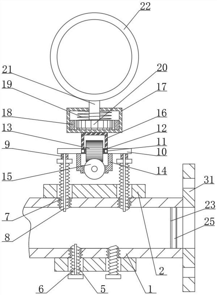
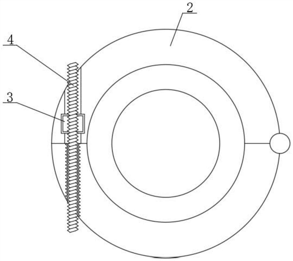
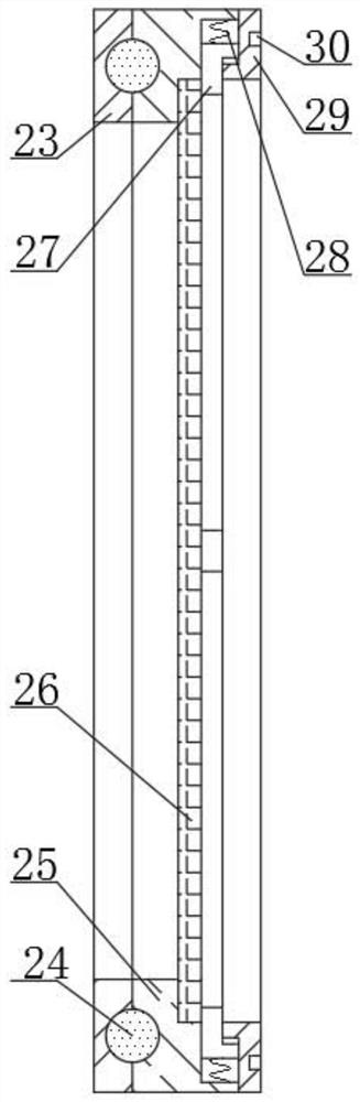
[0025] see Figure 1-5 , the present invention provides a technical solution:

[0026] A downhole long-term electromagnetic flowmeter for a water well distribution network, comprising a measuring tube 1, a mounting tube 2 is arranged on the outside of the measuring tube 1, a rotating block 3 is connected to the inside of the mounting tube 2 at the top, and a rotating block 3 is fixedly connected to the inside of the rotating block 3 The first threaded rod 4 i...


PUM


Abstract

The invention relates to the technical field of electromagnetic flowmeters, in particular to an underground long-acting electromagnetic flowmeter for a well separate injection network. The flowmeter comprises a measuring pipe, a mounting pipe is arranged on the outer side of the measuring pipe; a rotating block is rotationally connected to the inner side of the mounting pipe at the top end; the inner side of the rotating block is fixedly connected with a first threaded rod; a second threaded rod is arranged on the inner side of the mounting pipe at the bottom end; the inner side of the secondthreaded rod is fixedly connected with a first electrode; a third threaded rod is fixedly connected to the inner side of the mounting pipe at the top end; the inner side of the third threaded rod is slidably connected with a second electrode. The top end of the third threaded rod is fixedly connected with a rotary drum; the top end of the rotary drum is rotationally connected with a mounting plate. According to the flowmeter, with the arrangement of the mounting pipe, the rotating block, the first threaded rod, the first electrode and the third threaded rod, the convenience of device assemblyis improved, time and labor are saved, the device mounting efficiency is improved, downhole operation is facilitated, the device is fixed stably, and the use safety of the device is improved.

Description

technical field [0001] The invention relates to the technical field of electromagnetic flowmeters, in particular to an underground long-acting electromagnetic flowmeter for water well distribution network. Background technique [0002] Electromagnetic flowmeter is a new type of flow measuring instrument developed rapidly with the development of electronic technology in the 1950s and 1960s. Electromagnetic flowmeter is an instrument that uses the principle of electromagnetic induction to measure the flow rate of conductive fluid based on the electromotive force induced when the conductive fluid passes through an external magnetic field, because the measurement is not affected by changes in fluid density, viscosity, temperature, pressure and conductivity. There are no obstructing flow parts in the pipe, no pressure loss, and low requirements for straight pipe sections. It has unique adaptability to slurry measurement. Therefore, the demand for a long-term downhole long-term el...

Claims


Application Information

Patent Timeline
IPC IPC(8): G01F1/58G01F15/12E21B47/00
CPCG01F1/58G01F15/125E21B47/00
Inventor 黄世幸孙振郭流洋李育东刘田许娟
Owner 西安罗格石油仪器有限公司
Why Eureka
Try Eureka