
Micro light-emitting diode display panel and preparation method thereof

A technology for micro-LEDs and display panels, applied in electrical components, electric solid-state devices, circuits, etc., can solve the problems of low probability of driving the backplane, inability to adhere to the driving backplane, misalignment of electrodes on the micro-LED driving backplane, etc.

Active Publication Date: 2020-10-23
CHENGDU VISTAR OPTEOLECTRONICS CO LTD
View PDF9 Cites 5 Cited by
  • Summary
  • Abstract
  • Description
  • Claims
  • Application Information

AI Technical Summary

Problems solved by technology

[0004] The present application provides a micro-light emitting diode display panel and a preparation method thereof, which can solve the problem of the low probability of micro-light-emitting diodes transferring to the driving backplane in the prior art, the misalignment of micro-light-emitting diodes with the electrodes of the driving backplane, and the inability to adhere to the driving backplane. board problem

Method used


Image

  • Micro light-emitting diode display panel and preparation method thereof
  • Micro light-emitting diode display panel and preparation method thereof
  • Micro light-emitting diode display panel and preparation method thereof

Examples


Embodiment Construction

[0021] The following will clearly and completely describe the technical solutions in the embodiments of the present application with reference to the accompanying drawings in the embodiments of the present application. Obviously, the described embodiments are only part of the embodiments of the present application, not all of them. Based on the embodiments in this application, all other embodiments obtained by persons of ordinary skill in the art without making creative efforts belong to the scope of protection of this application.

[0022] The terms "first" and "second" in this application are only used for descriptive purposes, and should not be understood as indicating or implying relative importance or implicitly specifying the quantity of indicated technical features. Thus, the features defined as "first" and "second" may explicitly or implicitly include at least one of these features.

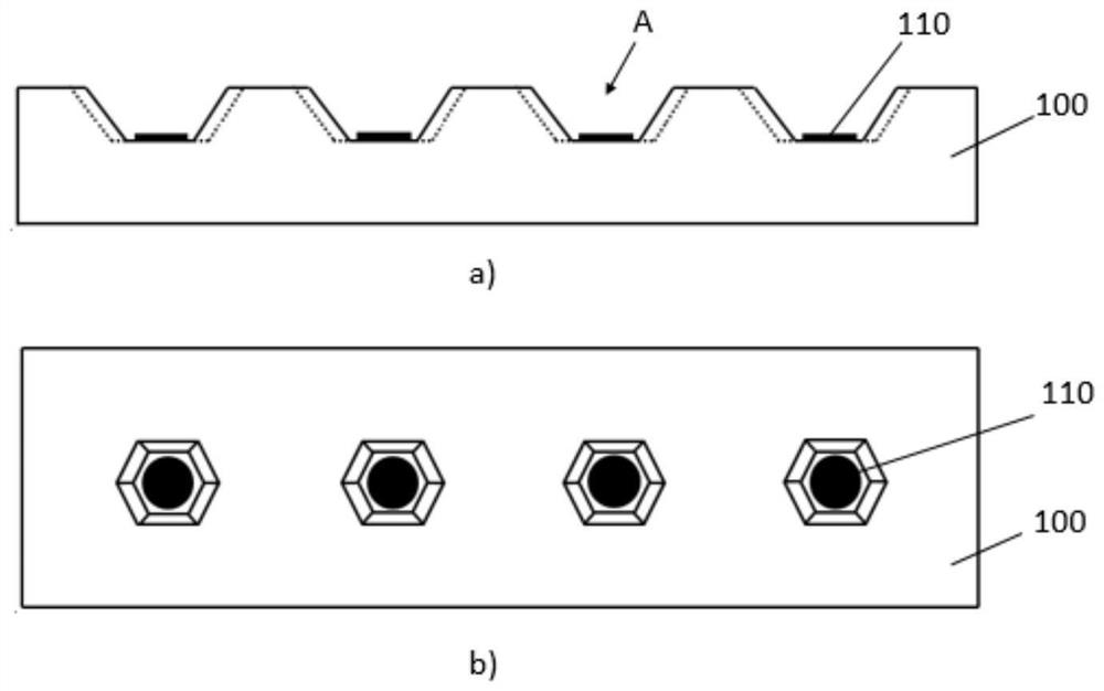
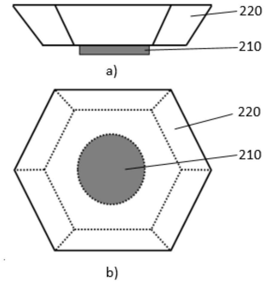
[0023] For an example of this application, see figure 1 and figure 2 , figure 1 I...


PUM


Abstract

The invention discloses a micro light-emitting diode display panel and a preparation method thereof, the micro light-emitting diode display panel comprises: a driving back plate, wherein one surface of the driving back plate is provided with a plurality of grooves, the bottom of each groove is provided with a first magnetic electrode, and the sectional dimensions of the grooves are gradually increased from bottom to top; and a micro light-emitting diode which is embedded into the groove of the driving back plate, wherein a second magnetic electrode is arranged at one end of the micro light-emitting diode, the second magnetic electrode and the first magnetic electrode are in contact with each other, and the maximum section size of the micro light-emitting diode is not smaller than that of the groove. In this way, the transfer efficiency of the micro light-emitting diode can be improved, and large-scale transfer is achieved.

Description

technical field [0001] The present application relates to the field of micro-light-emitting diode transfer technology, in particular to a micro-light-emitting diode display panel and a preparation method thereof. Background technique [0002] Micro LED (Micro LED) technology refers to a micro-sized LED array integrated with high density on a substrate. Micro LED is expected to lead the next generation of display technology due to its extremely high luminous efficiency and extremely long display life. [0003] Micro-LEDs are usually mass-transferred after fabrication, specifically transferring a large number of micro-LED chips to a driving circuit board to form a micro-LED array. When the current fluid assembly method transfers the micro-light-emitting diodes, because the micro-light-emitting diodes are randomly distributed in the fluid, the production efficiency of the micro-light-emitting diodes may be low. Contents of the invention [0004] The present application provi...

Claims


Application Information

Patent Timeline
Patent Type & Authority Applications(China)
IPC IPC(8): H01L33/62H01L33/48H01L25/13
CPCH01L33/62H01L33/48H01L25/13H01L2933/0066H01L2933/0033H01L2224/95085H01L2224/95136H01L2224/95144H01L33/483H01L33/40H01L27/156
Inventor 樊腾邢汝博郭恩卿韦冬
Owner CHENGDU VISTAR OPTEOLECTRONICS CO LTD
Learn More