Digital signal transmission processing equipment link fault analysis and alarm method

A technology for dealing with equipment and link failures, applied in digital transmission systems, transmission systems, data exchange networks, etc., can solve problems such as complex situations and inconvenient judgments

Active Publication Date: 2020-10-23
湖南双菱电子科技有限公司
View PDF15 Cites 0 Cited by
  • Summary
  • Abstract
  • Description
  • Claims
  • Application Information

AI Technical Summary

Problems solved by technology

[0004] However, there are some defects in the fault analysis and positioning method in the existing "integrated monitoring system". For example, when the upstream equipment has no signal output, it will cause all downstream equipment using this signal to have no signal input and output, resulting in a large number of alarm information. If there is no It is difficult to judge the source of the error with a complete topology map, and when there are multiple device failures, the...

Method used


Image

  • Digital signal transmission processing equipment link fault analysis and alarm method
  • Digital signal transmission processing equipment link fault analysis and alarm method
  • Digital signal transmission processing equipment link fault analysis and alarm method

Examples


Embodiment 1

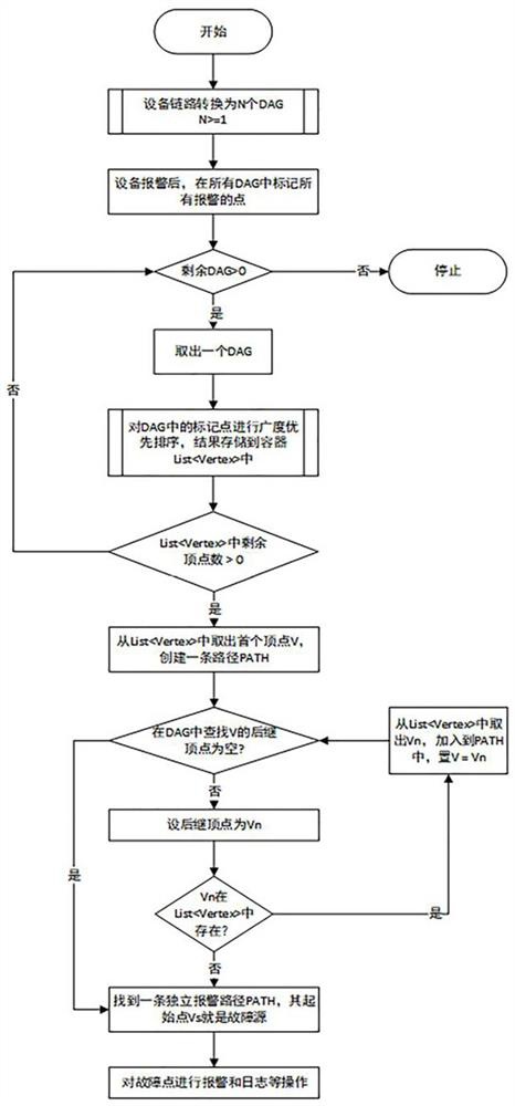
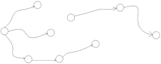
[0036] Such as figure 1 and figure 2 As shown, a digital audio and video signal transmission processing equipment link failure analysis and alarm method, including the following steps:

[0037] Step 1: Convert the device link into N DAGs, the device link includes n devices and m signal connections between devices, and n devices (Dev[i]) can be converted into n DAGs Independent node Vertex[i], m signal connection lines can be converted into m edges Edge[j], the edge Edge[j] connects two corresponding nodes in the DAG, and the flow direction of the edge is also the flow direction of the signal , n independent nodes Vertex[i] and m edges Edge[j] constitute the data structure G, if there are N relatively independent sub-links in the device link, and there are no edges connecting the sub-links , then in G, there will also be N independent DAGs (N>=1);

[0038] Step 2: Alarm signal mark. When the monitoring agent detects an abnormality in a certain device, it will report the abn...

Embodiment 2

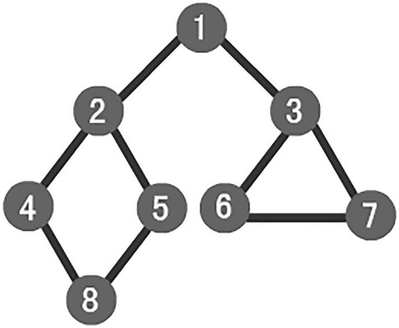
[0046] On the basis of Example 1, such as image 3 As shown, the breadth-first traversal described in step 3 is a traversal strategy for connected graphs, starting from the starting node V0, and traversing the wider area around it radially, that is, starting from V0, Visit the unvisited adjacent points W1, W2, ..., Wk of V0; then, visit the unvisited adjacent points sequentially from W1, W2, ..., Wk. Specific steps are as follows:

[0047] 1: Visit the initial node v and mark the node v as visited;

[0048] 2: Node v enters the queue;

[0049] 3: When the queue is not empty, continue to execute, otherwise the algorithm ends;

[0050] 4: Get out of the queue and get the queue head node u;

[0051] 5: Find the first adjacent node w of node u;

[0052] 6: If the adjacent node w of node u does not exist, then go to step 3, otherwise execute the following three steps in a loop:

[0053] 1). If the node w has not been visited, then visit the node w and mark it as visited;

[...

Embodiment 3

[0059] On the basis of embodiment 1, the concrete steps of described step 4 are as follows:

[0060] A: Create an empty path PATH, and take out the first node V1 in C1 and add it to PATH;

[0061] B: In the graph DAG where V1 is located, find the set of successor nodes {Vnext1, Vnext2,...Vnextm} of V1. If the successor node is in the set C1, take this node out of C1 and add it to the path in PATH;

[0062] C: Repeat steps A and B until there is no successor node belonging to C1, thus finding an independent path PATH;

[0063] D: Repeat steps A, B, and C until the nodes in the C1 set are empty.


PUM


Abstract

The invention belongs to the technical field of digital instrument equipment monitoring, and particularly relates to a digital audio and video signal transmission processing equipment link fault analysis and alarm method, which comprises the following steps of: 1, converting an equipment link into N DAGs; 2, marking an alarm signal node; 3, performing breadth-first traversal on the DAG which is being processed, and sorting alarm signal nodes into a set C1; 4, using an independent path search algorithm for the set C1; and 5, if the number N of the DAGs in the data structure G in the step 1 is greater than 1, repeating the steps 2-4, finding out a fault path and a fault source in each DAG, and ending the algorithm. The fault source can be accurately analyzed and positioned, the processing efficiency is improved, a user can be helped to rapidly find the fault source, the fault response time is shortened, the safety of the whole system is improved, fault alarm information display can be optimized, and the user cannot receive a lot of disordered alarm information.

Description

technical field [0001] The invention belongs to the technical field of instrument and equipment monitoring, and in particular relates to a link failure analysis and alarm method of digital signal transmission processing equipment. Background technique [0002] With the rapid development of information technology, there are more and more services related to the transmission and processing of digital audio and video signals, and the systems are becoming more and more complex. In the transmission link of digital audio and video signals, multiple signal sources are required for distribution, switching, processing and scheduling, and there are as few as several or as many as dozens of various professional equipment for collaborative processing. Any failure of any of these devices may affect the final output signal, and it is unrealistic to monitor and manage so many devices manually. Therefore, various comprehensive information solutions for monitoring, alarming and processing h...

Claims


Application Information

Patent Timeline
IPC IPC(8): H04L12/24H04L12/26
CPCH04L41/0631H04L41/0677H04L41/0823H04L43/0823H04L43/50
Inventor 周建国徐理
Owner 湖南双菱电子科技有限公司
Why Eureka
Try Eureka