Agricultural peanut turnover, cleaning and beating-off device

A technology of flipping and cleaning peanuts, which is applied in agriculture, agricultural machinery and tools, and applications. It can solve the problems of insufficient cleaning, easy knocking of peanuts, and falling of peanuts, so as to improve safety, accuracy, and high work efficiency. , good safety effect

Inactive Publication Date: 2020-10-27
谢秀荣
View PDF1 Cites 2 Cited by
  • Summary
  • Abstract
  • Description
  • Claims
  • Application Information

AI Technical Summary

Problems solved by technology

The device fixes the peanut seedlings through the fixing mechanism, knocks down the peanuts through the knocking device, and is also equipped with a toggle mechanism to toggle and clean the peanuts, thereby achieving the effect of saving time and automatically cleaning the peanuts, but When the device cle

Method used


Image

  • Agricultural peanut turnover, cleaning and beating-off device
  • Agricultural peanut turnover, cleaning and beating-off device
  • Agricultural peanut turnover, cleaning and beating-off device

Examples


Embodiment 1

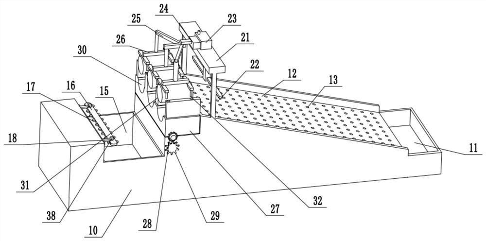
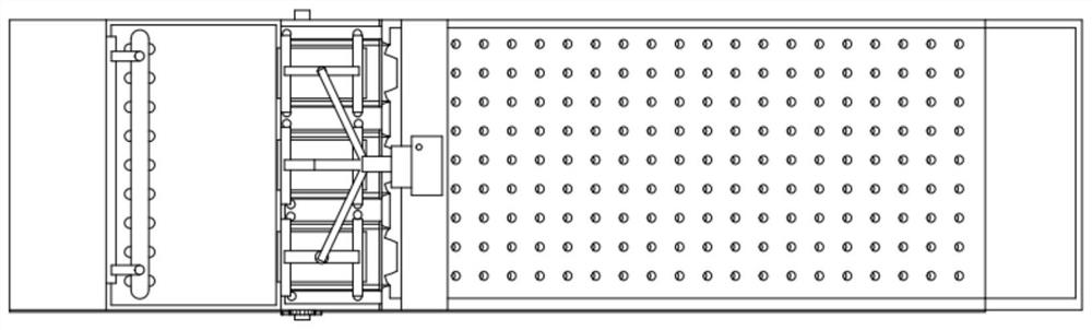
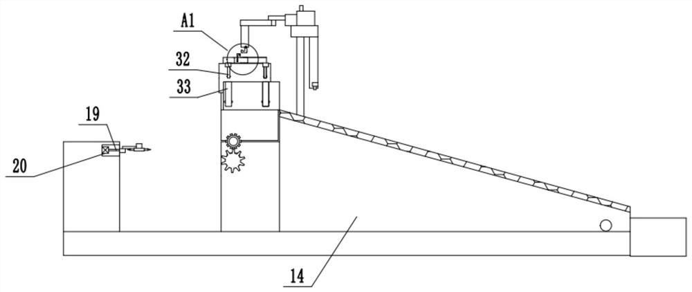
[0026] see Figure 1-4, a device for turning over, cleaning and knocking down peanuts for agriculture, comprising a base 10, a water spray row 22, and a cutting knife 17; the upper left side of the base 10 is provided with a group of second collecting tanks for storing the knocked-off peanuts downwards 15. On the top right side of the base 10, a set of blanking plates 12 with high left and low right are fixedly installed. The surface of the blanking plate 12 is provided with several sets of water filter holes 13 evenly distributed for filtering peanuts and muddy water. The bottom of the material plate 12 is communicated with a waste water chamber 14 arranged inside the base 10 , through which the muddy water from washing peanuts on the material plate 12 is collected. The bottom end of the blanking plate 12 is connected with a first collecting tank 11 fixed on the right end of the base 10 . The upper left side of the blanking plate 12 is fixedly installed with a group of top b...

Embodiment 2

[0029] On the basis of Embodiment 1, the inner surface of the peanut trough 30 and the outer surface of the pressure rod 31 are wrapped with a layer of rubber pads, which are used to prevent the two from contacting each other when the peanut branches and leaves are placed inside it. Large, the leaves are squeezed out of the water or the branches are broken, flowing and scattered randomly, which is not conducive to the safe operation of the equipment.

[0030] The working principle of the present invention is: when in use, first place the branches and leaves of the peanuts to be cleaned and knocked down inside the peanut trough 30, and place the fruit part under the water spray row 22 on the right side of the peanut trough 30, and then start the elevator 24 drives the pressing rod 31 connected to the bottom of the connecting frame 25 to move downwards, the branches and leaves of the peanuts are clamped and stabilized by the pressing rod 31 and the peanut groove 30, and then the ...


PUM


Abstract

The invention relates to the technical field of agricultural equipment and discloses an agricultural peanut turnover, cleaning and beating-off device. The device comprises a base, a water spray row and cutters; the bottom end of a discharging plate is connected with a first collection groove fixed to the tail end of the right side of the base, a top plate which is placed in the front is fixedly mounted at the upper part of the left side of the discharging plate through a bracket, a water tank is fixedly mounted in the middle of the top of the top plate, a peanut seat adopting a rectangular structure is arranged at the top of the left side of the discharging plate, multiple peanut grooves adopting semicircular structures are formed in the upper side of the peanut seat from front to back atequal intervals, and a press rod is arranged on the upper side of the inside of each peanut groove; and a driven gear is fixedly mounted on the front side of a rotating shaft, the lower side of the driven gear is meshed with a driving gear, a second collection groove is formed below the left side of the peanut seat, a transmission plate is arranged on the left side of the top of the second collection groove, and a circle of cutters for cutting off peanut fruits to allow the peanut fruits to fall off are arranged on the outer ring of the middle of the transmission plate.

Description

technical field [0001] The invention relates to the technical field of agricultural equipment, in particular to an agricultural peanut turning, cleaning and knocking-off device. Background technique [0002] The objects of labor in agriculture are living animals and plants, and the products obtained are the animals and plants themselves. Agriculture is the basic industry that supports the construction and development of the national economy. After the peanuts in agriculture are pulled out, the peanuts need to be picked manually. It takes a lot of time to pick the peanuts manually, and the peanuts need to be cleaned manually after picking. [0003] Chinese patent (notification number: CN 108142108 A, announcement date: 2018.06.12) discloses an agricultural peanut knocking device, including a bottom plate, etc.; a box is installed on the top of the bottom plate, and a mounting rod is installed on the left side of the top of the box. A stop frame is installed on the top of the...

Claims


Application Information

Patent Timeline
IPC IPC(8): A23N12/06A01F11/00
CPCA01F11/00A23N12/06
Inventor 谢秀荣
Owner 谢秀荣
Why Eureka
Try Eureka