
Automatic bar stock processing machine tool

A bar material processing and processing machine technology, applied in the field of automatic bar material processing machine tools, can solve the problems of poor feeding effect, low bar material utilization rate, and troublesome processing operations.

Pending Publication Date: 2020-10-27
兰溪瑞鼎机床股份有限公司
View PDF0 Cites 3 Cited by
  • Summary
  • Abstract
  • Description
  • Claims
  • Application Information

AI Technical Summary

Problems solved by technology

[0002] At present, the common bar material processing needs to manually send the bar material to the inclined material guide frame, and the bar material can roll to the feeding plate after passing through the material guide frame; due to the certain inertia of the bar material during the rolling process, The bar is easy to roll out of the feeding plate, and the inertia of the bar of different specifications is different during the rolling process, which will cause the bar to roll to different positions on the feeding plate, which is inconvenient for the subsequent conveying operation of the feeding plate, and the feeding effect is poor; Moreover, after the bar is sent to the processing machine tool, it is first cut to a fixed length and then manually sent to the CNC machine tool for processing. For material operation, it is necessary to reserve a certain length of bar material for clamping, resulting in the problem of low bar material utilization
Therefore, the existing bar material processing device has the problems of poor feeding effect, troublesome processing operation, high labor intensity and low bar material utilization rate

Method used


Image

  • Automatic bar stock processing machine tool
  • Automatic bar stock processing machine tool
  • Automatic bar stock processing machine tool

Examples


Embodiment Construction

[0024] The present invention will be further described below in conjunction with the accompanying drawings and embodiments, but not as a basis for limiting the present invention.

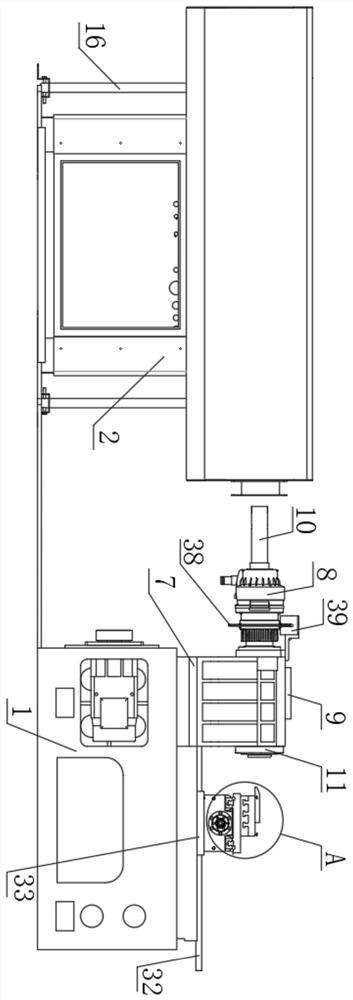
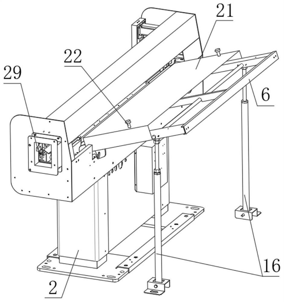
[0025] Example. An automatic bar processing machine tool, constituted as Figures 1 to 8Shown, comprise processing frame 1, one side of processing frame 1 is provided with feeding frame 2; Feeding frame 2 is provided with horizontal feeding plate 3, and the top of feeding plate 3 is provided with pusher; Said Feeding plate 3 is V-shaped setting, and supporting block 4 is all fixed on the bottom surface of feeding plate 3 two ends; A tilted No. 1 telescopic rod 5 is connected between the sides and the feeding frame 2; an inclined material guide frame 6 is provided on the side corresponding to the feeding plate 3 on the feeding frame 2; the processing frame 1 A connecting seat 7 is fixed on the connecting seat 7, and a main shaft 8 is rotatably connected to the connecting seat 7; an encoder 9 is con...


PUM


Abstract

The invention discloses an automatic bar stock processing machine tool. The automatic bar stock processing machine tool comprises a processing machine frame, and a loading machine frame is arranged onone side of the processing machine frame; a feeding plate is arranged on the loading machine frame, and a pushing device is arranged above the feeding plate; the feeding plate is arranged in a V shape, and a first telescopic rod is connected to a supporting block of the bottom surface of the feeding plate; a main shaft is rotatably arranged on the processing machine frame, and an encoder is connected to the main shaft; a transverse sliding seat is arranged on the processing machine frame, and a transverse pushing device is connected between the transverse sliding seat and the processing machine frame; a longitudinal sliding seat is arranged above the transverse sliding seat, and a longitudinal pushing device is connected between the longitudinal sliding seat and the transverse sliding seat; and a plurality of turning tools are arranged on the top surface of the longitudinal sliding seat. The automatic bar stock processing machine tool can improve the feeding effect, and further has the advantages that the processing operation is relatively convenient, the labor strength is small, the bar stock utilization rate is high, the using is relatively convenient, the application range is wide, the control precision is high, the processing precision is high and the discharging is relatively convenient.

Description

technical field [0001] The invention relates to a processing machine tool, in particular to an automatic bar material processing machine tool. Background technique [0002] At present, the common bar material processing needs to manually send the bar material to the inclined material guide frame, and the bar material can roll to the feeding plate after passing through the material guide frame; due to the certain inertia of the bar material during the rolling process, The bar is easy to roll out of the feeding plate, and the inertia of the bar of different specifications is different during the rolling process, which will cause the bar to roll to different positions on the feeding plate, which is inconvenient for the subsequent conveying operation of the feeding plate, and the feeding effect is poor; Moreover, after the bar is sent to the processing machine tool, it is first cut to a fixed length and then manually sent to the CNC machine tool for processing. For material ope...

Claims


Application Information

Patent Timeline
IPC IPC(8): B23B5/08B23Q7/00B23Q7/08B23Q7/14
CPCB23B5/08B23Q7/001B23Q7/003B23Q7/006B23Q7/08B23Q7/1405
Inventor 郑伟民
Owner 兰溪瑞鼎机床股份有限公司
Learn More