
Automatic horizontal milling and boring machine

A milling and boring machine and horizontal technology, which is applied in the field of automatic horizontal milling and boring machines, can solve the problems of different workpiece structures, reduced workpiece processing efficiency, time-consuming and labor-intensive and other problems.

Pending Publication Date: 2020-10-27
杨安龙
View PDF7 Cites 3 Cited by
  • Summary
  • Abstract
  • Description
  • Claims
  • Application Information

AI Technical Summary

Problems solved by technology

[0003] At present, the ordinary horizontal milling and boring machines on the market need to fix the workpiece on the upper surface of the processing table when processing the workpiece, and then start the milling and boring machine to drive the tool to process the workpiece. However, the existing workpieces are used in different fields. The structure of the workpiece will be different, so when the workpiece is processed with different shapes on the surface of the horizontal milling and boring machine processing table, it is necessary to loosen and adjust the clamp on the upper surface of the processing table and rotate the workpiece, and then re-clamp the workpiece through the clamp. This processing process is not only time-consuming and laborious, but also brings a lot of inconvenience to the operator, and also greatly reduces the processing efficiency of the workpiece. Therefore, an automatic horizontal type is needed to solve the above-mentioned problems.

Method used


Image

  • Automatic horizontal milling and boring machine
  • Automatic horizontal milling and boring machine
  • Automatic horizontal milling and boring machine

Examples


Embodiment Construction

[0025] The following will clearly and completely describe the technical solutions in the embodiments of the present invention with reference to the accompanying drawings in the embodiments of the present invention. Obviously, the described embodiments are only some, not all, embodiments of the present invention. Based on the embodiments of the present invention, all other embodiments obtained by persons of ordinary skill in the art without making creative efforts belong to the protection scope of the present invention.

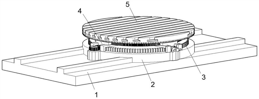
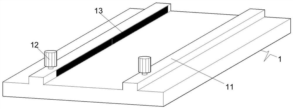
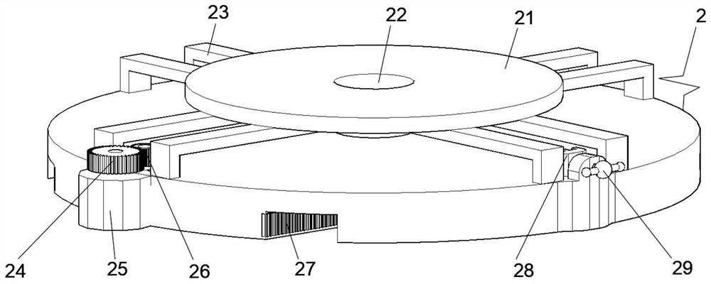
[0026] see Figure 1-6 , an embodiment provided by the present invention: an automatic horizontal milling and boring machine, including a base 1, a chassis 2, an adjustment plate 3, a positioning block 4 and a processing table 5, the chassis 2 is movably engaged and connected to the top surface of the base 1, and the adjustment The disc 3 is movably connected to the top center of the chassis 2, the positioning block 4 is movably connected to the edge of the to...


PUM


Abstract

The invention relates to the technical field of milling and boring machine equipment, in particular to an automatic horizontal milling and boring machine. The automatic horizontal milling and boring machine comprises a base, a baes plate, an adjusting plate, positioning blocks and a machining table, wherein the base plate is movably engaged with the top face of the base, the adjusting plate is movably clamped to the center of the top of the base plate, and the positioning blocks are movably clamped to the edge of the top face of the base plate; and the machining table is rotationally installedin the center of the top face of the base plate, guide rails are symmetrically arranged on the top face of the base, chains are movably installed in the side faces of the guide rails, and a first driving motor is fixedly installed on the edge of one end of the top of each guide rail. By controlling rotation of the adjusting plate, the four sets of positioning blocks can position the machining table, so that the machining table is conveniently rotated to change the machining angle of a workpiece, repeated mounting and dismounting of a clamp are avoided, and the machining efficiency of the workpiece is improved.

Description

technical field [0001] The invention relates to the technical field of milling and boring machine equipment, in particular to an automatic horizontal milling and boring machine. Background technique [0002] The horizontal milling and boring machine is a processing tool commonly used in the processing industry. It combines the two functions of the boring machine and the milling machine in one, which makes the processing efficiency higher and the precision better, and greatly improves the product quality and labor efficiency. The horizontal milling machine The boring machine is a universal machine tool, which can perform cutting processes such as drilling, boring, reaming, reaming, countersinking, milling, and threading on large parts such as boxes, shells, and machine bases. This type of machine tool is widely used in energy, transportation, heavy-duty, petrochemical machinery and other industries, and is the key equipment for processing box-type parts. [0003] At present,...

Claims


Application Information

Patent Timeline
IPC IPC(8): B23Q16/06B23B39/02
CPCB23B39/02B23Q16/06
Inventor 杨安龙冯建国
Owner 杨安龙
Learn More