Refractory ceramic plunger machine

A technology of high-temperature-resistant ceramics and plunger machines, applied in the field of high-temperature structural ceramics, can solve problems such as unqualified quality of porcelain clay, danger, and rupture of the extrusion port.

Active Publication Date: 2020-10-27
衡阳阳光陶瓷有限公司
View PDF14 Cites 1 Cited by
  • Summary
  • Abstract
  • Description
  • Claims
  • Application Information

AI Technical Summary

Problems solved by technology

[0002] The high temperature resistant ceramic plunger machine is a device used to remove the air bubbles contained in the ceramic soil in the manufacture of high temperature resistant ceramics. Specifically, the ceramic soil is put into the conical barrel, and the ceramic soil is squeezed out of the conical cavity by extrusion. During the extrusion process, the air in the ceramic soil is extruded by the porcelain clay and released from the upper end to achieve the effect of removing air. However, because the outlet of the front end of the conical cavity of the high-temperature ceramic plunger machine is contracted, even if the column The front end of the plug pump is also equipped with a shr...

Method used


Image

  • Refractory ceramic plunger machine
  • Refractory ceramic plunger machine
  • Refractory ceramic plunger machine

Examples


Embodiment 1

[0024] as attached figure 1 To attach Figure 5 Shown:

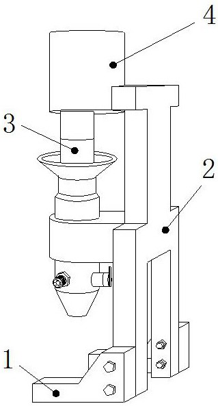
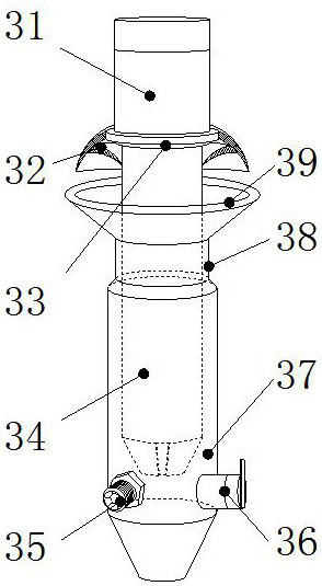
[0025] The present invention provides a high-temperature resistant ceramic plunger machine, the structure of which includes a support foot 1, a support frame 2, a plunger device 3, and a driver 4. It is embedded and connected to the left end of the middle part of the support frame 2, and the driver 4 is axially connected to the upper end of the plunger device 3. The plunger device 3 includes a plunger pump 31, an anti-overflow cap 32, a fixed ring 33, a plunger 34, an exhaust Port 35, pressure relief port 36, tapered barrel 37, connecting ring 38, bell mouth 39, the lower end of the plunger pump 31 is connected with the anti-overflow cap 32 through the fixing ring 33, the upper end of the plug column 34 is connected with the column The lower end of the plug pump 31 is embedded and connected, the exhaust port 35 is threadedly connected to the lower end of the conical barrel 37, the pressure relief port 36 is movably eng...

Embodiment 2

[0032] as attached Figure 6 to attach Figure 7 Shown:

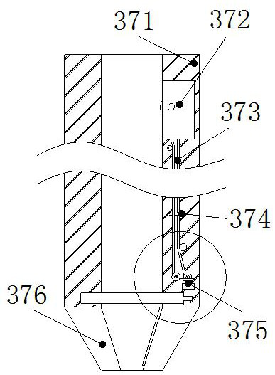
[0033] Wherein, the rotating ring 75e includes a ring body e1, a contraction piece e2, and a scraping piece e3, the ring body e1 is embedded and connected with the inner side of the outer cover 371, and the shrinking piece e2 is embedded and connected with the right end of the ring body e1. The upper end of the scraping piece e3 is welded to the inside of the shrinking piece e2, and the scraping piece e3 is slidably connected to the left side of the shrinking piece e2, and is installed at an inclined angle. The angle is the same as that of the extrusion port 376, so that the scraping The sheet e3 can keep in contact with the surface of the inner wall of the extrusion port 376, which is beneficial to scrape off the porcelain mud adhered to the inner wall behind the plunger.

[0034] Wherein, the scraping piece e3 includes a support block r1, a connecting piece r2, a deflection shaft r3, and a vibrating column r4. Weld...


PUM


Abstract

The invention discloses a refractory ceramic plunger machine. The refractory ceramic plunger machine structurally comprises a support foot, a supporting frame, a plunger device and a driver, wherein the right end of the support foot is connected with the lower end of the supporting frame through bolts, and the driver is connected with the upper end of the plunger device through a shaft. The rotation of a rotating ring can scrape and clean the ceramic mud on the inner wall of an extrusion port, a large amount of porcelain clay is prevented from adhering on the surface of the outer side of the extrusion port, after using, it is necessary to reach into the interior for cleaning so as to prevent the situation that it is difficult to clean the ceramic mud on the surface of the inner wall of theextrusion port due to air drying, thus a certain dangerousness exists, a supporting block in a ring body drives a connecting piece to rotate to close to the surface of the inner wall of the extrusionport to rotate to generate vibration, dried ceramic mud is conveniently vibrated to reduce the adhesion force with the inner wall of the extrusion port, finally, the dried ceramic mud is shaken off,and the situation that the dried ceramic mud has certain strength, under the condition of unclear cleaning, the extrusion port can be broken by extruding again, the extrusion resistance is reduced, and the extruded ceramic mud is unqualified is prevented.

Description

technical field [0001] The invention belongs to the field of high-temperature structural ceramics, and more specifically relates to a high-temperature-resistant ceramic plunger machine. Background technique [0002] The high temperature resistant ceramic plunger machine is a device used to remove the air bubbles contained in the ceramic soil in the manufacture of high temperature resistant ceramics. Specifically, the ceramic soil is put into the conical barrel, and the ceramic soil is squeezed out of the conical cavity by extrusion. During the extrusion process, the air in the ceramic soil is extruded by the porcelain clay and released from the upper end to achieve the effect of removing air. However, because the outlet of the front end of the conical cavity of the high-temperature ceramic plunger machine is contracted, even if the column The front end of the plug pump is also equipped with a shrinking plug, but the porcelain clay will still leave a layer of porcelain clay o...

Claims


Application Information

Patent Timeline
IPC IPC(8): B28B7/38B28B3/26B28B3/24
CPCB28B3/24B28B3/26B28B7/382
Inventor 翁红英
Owner 衡阳阳光陶瓷有限公司
Why Eureka
Try Eureka