Cavity automatic foaming visual positioning device and automatic foaming method

A technology of visual positioning and foaming device, applied in the field of foaming process equipment, can solve the problems of low efficiency of manual foaming operation, influence of positioning equipment, unstable foaming quality, etc.

Active Publication Date: 2020-10-27
SHANGHAI FANUC ROBOTICS
View PDF11 Cites 2 Cited by
  • Summary
  • Abstract
  • Description
  • Claims
  • Application Information

AI Technical Summary

Problems solved by technology

[0002] At present, in the foaming operation of the body cavity, due to the low efficiency of the manual foaming operation, the unstable foaming quality and the hazards of the foaming material to human health, it is necessary to realize the automation of the foaming operation of the body cavity
However, in robot automation applications, some existing hand-held visual positioning devices cannot adapt to severe pollution conditions. Pollution conditions are likely to affect the positioning equipment and affect the accuracy of subsequent position positioning.

Method used


Image

  • Cavity automatic foaming visual positioning device and automatic foaming method
  • Cavity automatic foaming visual positioning device and automatic foaming method
  • Cavity automatic foaming visual positioning device and automatic foaming method

Examples


Embodiment Construction

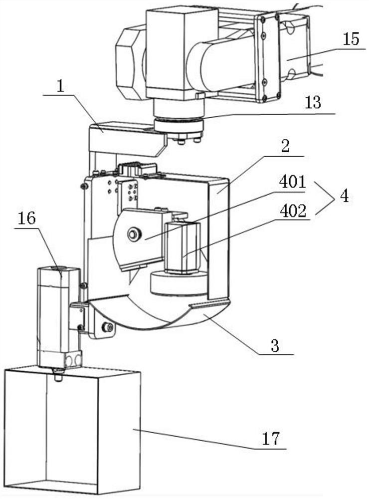
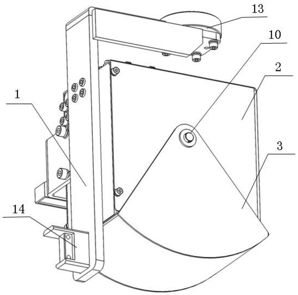
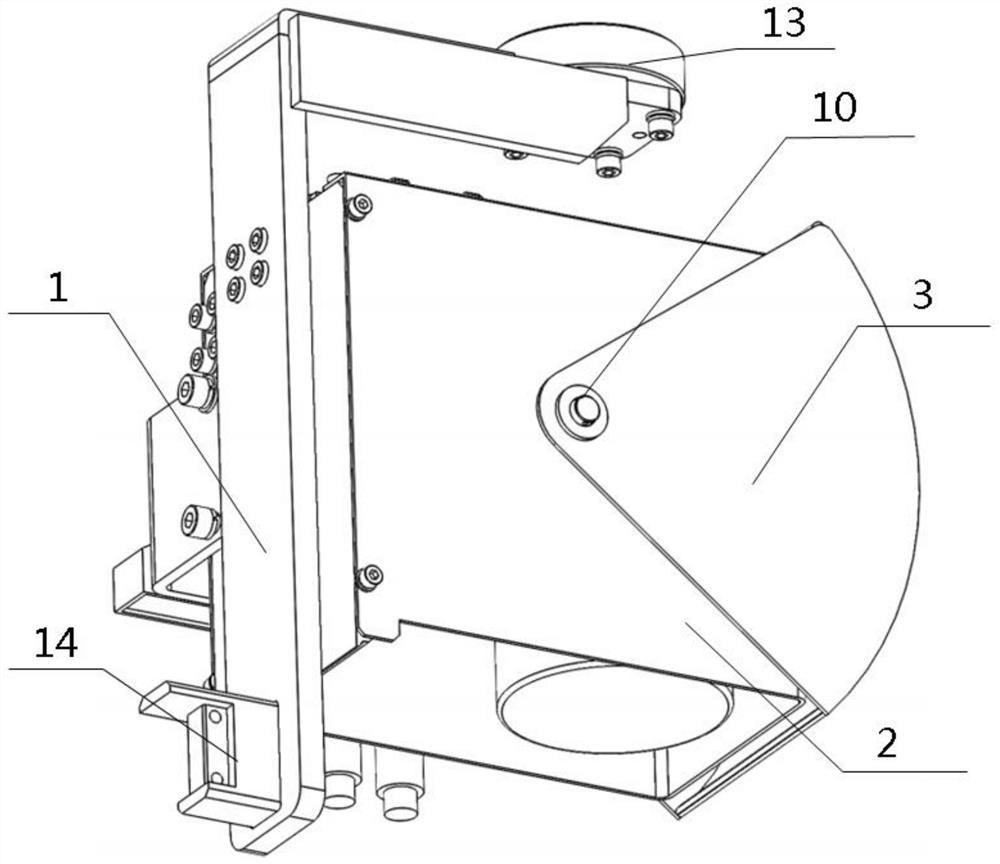
[0045] In order to make it easy to understand the technical means, creative features, goals and effects achieved by the present invention, the following examples are combined with the appended figure 1 to attach Figure 10 The cavity automatic foaming visual positioning device provided by the present invention is described in detail.

[0046] The serial numbers assigned to the components in this document, such as "first", "second", etc., are only used to distinguish the described objects and do not have any sequence or technical meaning. The "connection" and "connection" mentioned in this application all include direct and indirect connection (connection) unless otherwise specified. In describing the present invention, it is to be understood that the terms "upper", "lower", "front", "rear", "left", "right", "vertical", "horizontal", "top", The orientation or positional relationship indicated by "bottom", "inner", "outer", "clockwise", "counterclockwise", etc. is based on the...


PUM


Abstract

The invention discloses a cavity automatic foaming visual positioning device and an automatic foaming method, and belongs to the technical field of foaming process equipment. The cavity automatic foaming visual positioning device comprises a U industrial robot, a fixed cover shell, an industrial camera, a turnover cover shell and a foaming device. The U industrial robot is fixedly connected with afixed support. The fixed cover shell is fixedly arranged on the fixed support. A mounting cavity is formed in the fixed cover shell. An opening is formed in one side of the fixed cover shell. The industrial camera is arranged in the mounting cavity. A lens of the industrial camera faces the opening. The industrial camera is in communication connection with the industrial robot. The turnover covershell is movably connected with one end, provided with the opening, of the fixe cover shell. The turnover cover shell can movably and directly face the opening. The foaming device is fixedly connected with the fixed support. By means of the cavity automatic foaming visual positioning device and the automatic foaming method, automatic foaming operation of a cavity of a vehicle body is achieved, the foaming operation efficiency of the cavity of the vehicle body is improved, the foaming quality is guaranteed, and the harm of foaming operation on health of enterprise employees is avoided.

Description

technical field [0001] The invention relates to the technical field of foaming process equipment, in particular to a cavity automatic foaming visual positioning device and an automatic foaming method. Background technique [0002] At present, in the foaming operation of the body cavity, due to the low efficiency of the manual foaming operation, the unstable foaming quality, and the fact that the foaming material is harmful to human health, it is necessary to realize the automation of the foaming operation of the body cavity. However, in robot automation applications, some existing hand-held visual positioning devices cannot adapt to severe pollution conditions. Pollution conditions are likely to affect the positioning equipment and affect the accuracy of subsequent position positioning. Contents of the invention [0003] In view of the above-mentioned problems existing in the prior art, the aim is to provide a visual positioning device for automatic foaming of the cavity, ...

Claims


Application Information

Patent Timeline
Patent Type & Authority Applications(China)
IPC IPC(8): B29C44/34B29C44/36B29C44/60
CPCB29C44/34B29C44/35B29C44/367B29C44/60
Inventor 张宏徐文君毛照友赵风卫朱晖波刘鹏祥王鑫
Owner SHANGHAI FANUC ROBOTICS
Why Eureka
Try Eureka