Currentcollecting device capable of collecting current from upper part

A current receiving device and upper arm technology, which is applied to vehicle parts, transportation and packaging, electric vehicles, etc., can solve the problems of accelerating the bow head's descending speed, affecting the service life, and violent impact of the contact rail, etc.

Active Publication Date: 2020-10-27
ZHUZHOU ELECTRIC LOCOMOTIVE CO
View PDF11 Cites 1 Cited by
  • Summary
  • Abstract
  • Description
  • Claims
  • Application Information

AI Technical Summary

Problems solved by technology

[0003] At present, the flow-receiving mode of the current-receiving device is mainly side-side flow-receiving and bottom-side flow-receiving. Compared with the side-side flow-receiving device and the bottom-side flow-receiving device, the self-weight of the

Method used


Image

  • Currentcollecting device capable of collecting current from upper part
  • Currentcollecting device capable of collecting current from upper part
  • Currentcollecting device capable of collecting current from upper part

Examples


Embodiment Construction

[0037] The present invention will be described in detail below with reference to the accompanying drawings and examples. It should be noted that, in the case of no conflict, the embodiments of the present invention and the features in the embodiments can be combined with each other. For the convenience of description, if the words "up", "down", "left" and "right" appear in the following, it only means that the directions of up, down, left and right are consistent with the drawings themselves, and do not limit the structure.

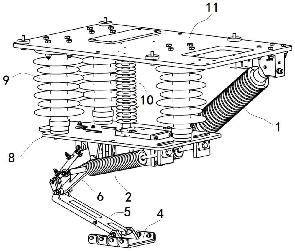
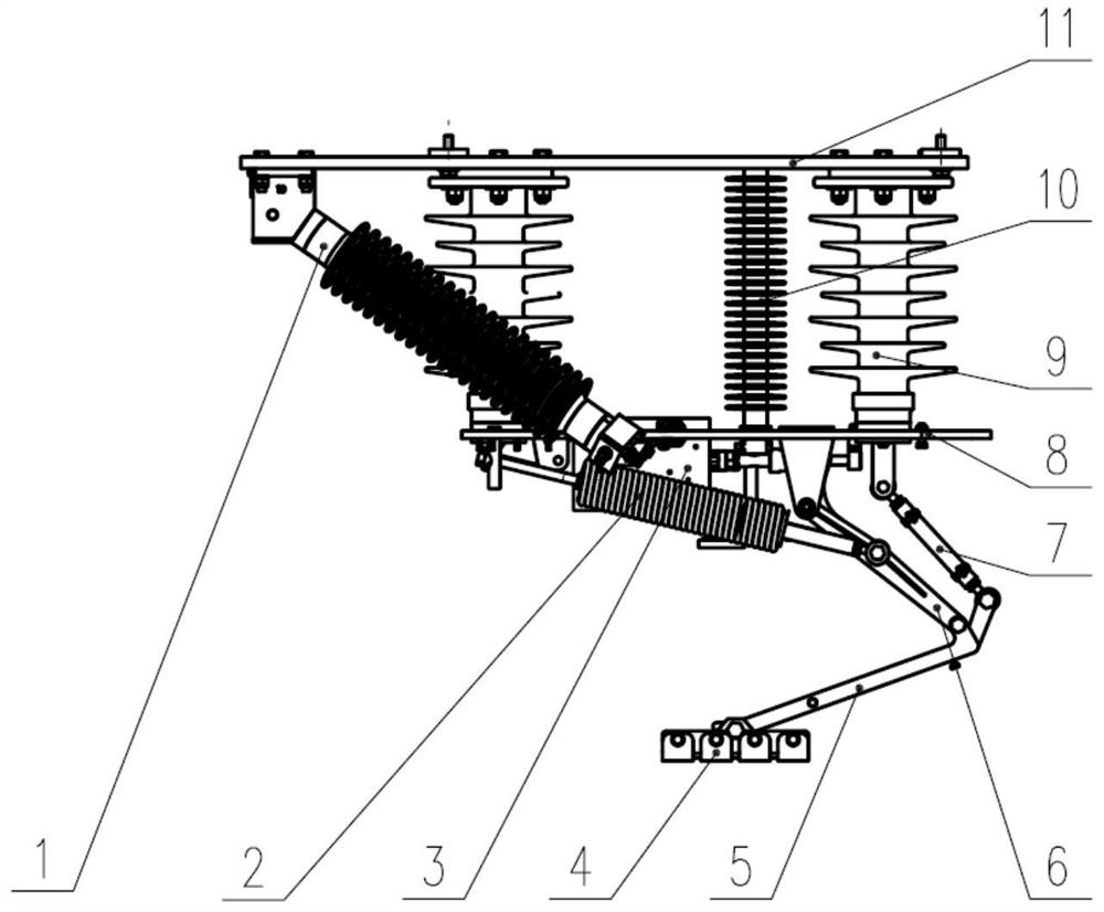
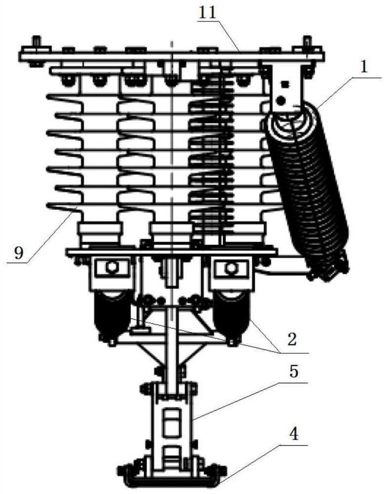
[0038] See attached Figure 1-4 As described above, the upper flow-receiving device of this embodiment includes an air distributor 1, a spring 2, a cylinder 3, a bow head 4, an upper arm 5, a lower arm 6, a tie rod 7, an underframe 8, and a support insulator 9 , Turn the insulator 10 and the bottom plate 11 and other parts. The bottom plate is installed on the roof mount, and the supporting insulator 9 is installed between the current receiving device c...


PUM


Abstract

The invention discloses a current collecting device capable of collecting current from the upper part. The current collecting device comprises a bottom plate, a bottom frame, a rotating insulator, a supporting insulator and a four-connecting-rod mechanism composed of an upper arm rod, a lower arm rod, a pull rod and a bottom frame. The two ends of the pull rod are hinged to the bottom frame and the upper arm rod respectively, and the connecting rod is connected with the rotating insulator. The extending end of the upper arm rod is provided with a pantograph head; an air cylinder is arranged onthe bottom frame, and an air cylinder piston rod of the air cylinder is simultaneously hinged with the lower arm rod and the connecting rod; the piston rod of the cylinder extends or contracts to drive the lower arm rod to rotate so as to enable the grounding device connected with the lower arm rod to expand or contract, and drives the connecting rod to rotate so as to drive the rotating insulator to rotate. An elastic element is connected between the bottom frame and the lower arm rod. According to the current collecting device, stable contact between the pantograph head and the contact railis achieved, and position signals such as stretching or retracting are sent to a vehicle.

Description

technical field [0001] The invention relates to a current receiving device at the upper part, which belongs to the field of electric locomotives. Background technique [0002] The way of receiving current of the current receiving device mainly depends on the position of the contact rail relative to the vehicle. [0003] At present, the flow-receiving mode of the current-receiving device is mainly side-side flow-receiving and bottom-side flow-receiving. Compared with the side-side flow-receiving device and the bottom-side flow-receiving device, the self-weight of the upper part flow-receiving device will accelerate during the opening process. The falling speed of the bow head is very easy to violently impact the contact rail, which seriously affects the service life of each part of the upper part of the current receiving device. At the same time, in order to facilitate the vehicle to make relevant logical judgments and carry out relevant follow-up instructions, the current r...

Claims


Application Information

Patent Timeline
IPC IPC(8): B60L5/30B60L5/32
CPCB60L5/30B60L5/32
Inventor 杨瀛瑜梁坤蒋聪健张海丰吕阶军林平李军王秋红陈明国冯叶
Owner ZHUZHOU ELECTRIC LOCOMOTIVE CO
Why Eureka
Try Eureka