Automatic running-in tooling structure

A tooling and conveying device technology, applied in the field of automatic running-in tooling structure, can solve the problems of low operation efficiency, waste of working time, and heavy weight of individual switches

Pending Publication Date: 2020-10-27
中山市永淇自动化设备有限公司
View PDF0 Cites 0 Cited by
  • Summary
  • Abstract
  • Description
  • Claims
  • Application Information

AI Technical Summary

Problems solved by technology

[0004] At present, when the switchgear is in use, manual work is used. Because the individual weight of the switch is too heavy, manual handling is a waste of working time and reduces work efficiency. In addition, when performing performance tests,...

Method used

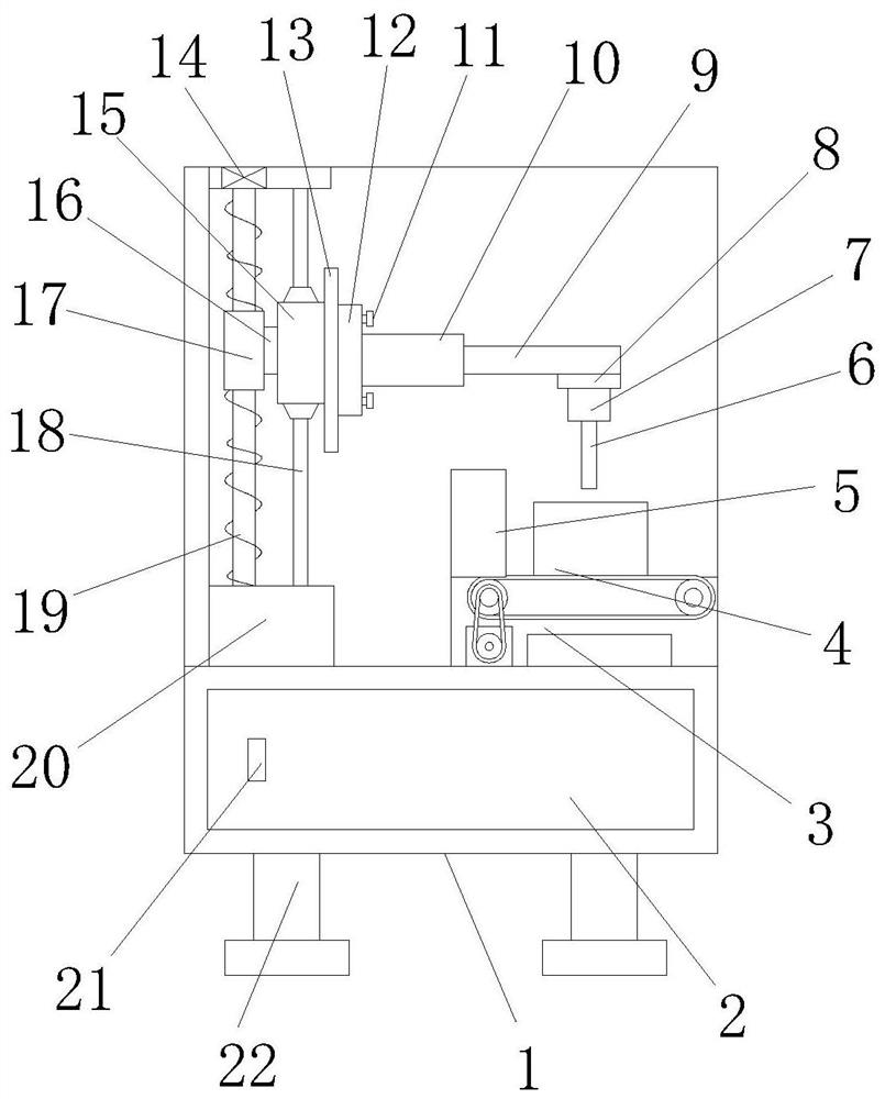
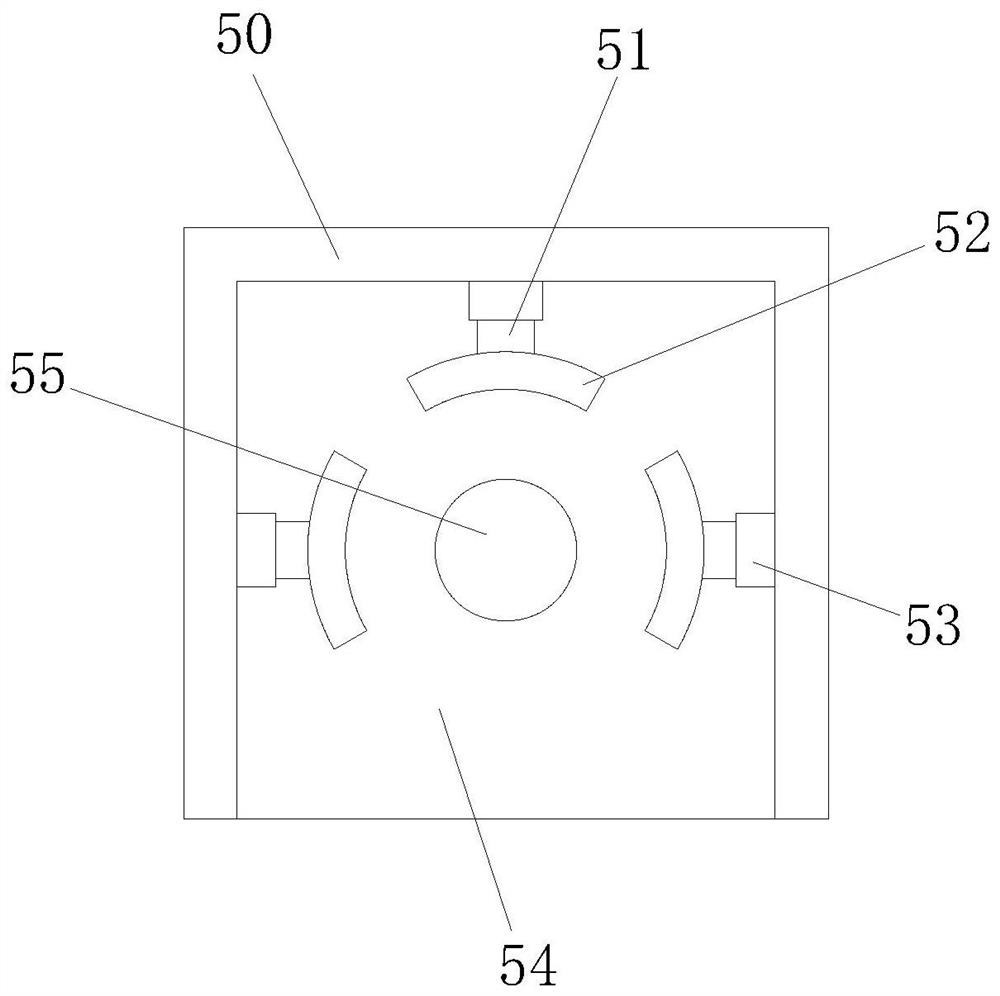
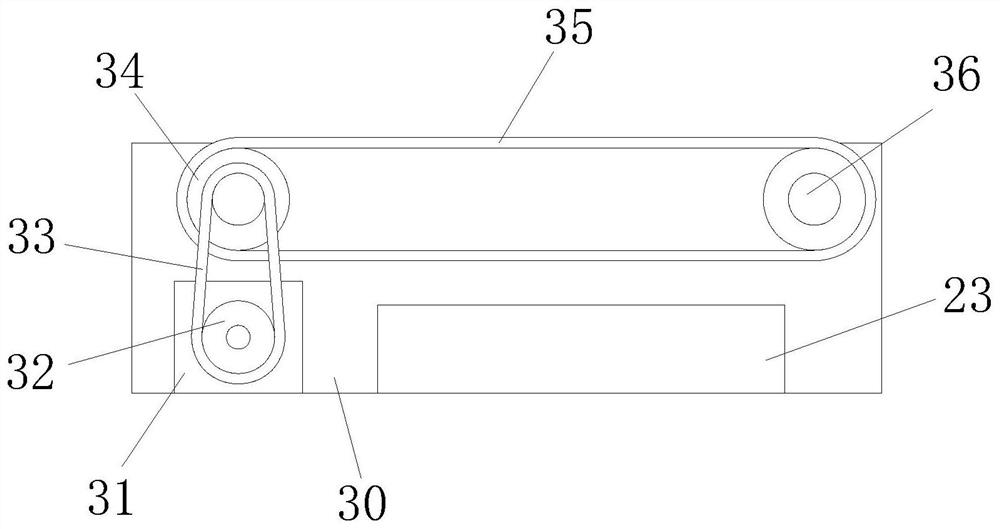

Image

  • Automatic running-in tooling structure
  • Automatic running-in tooling structure
  • Automatic running-in tooling structure

Examples


Embodiment Construction

[0027] In order to make the object, technical solution and advantages of the present invention clearer, the present invention will be further described in detail below in conjunction with the accompanying drawings and embodiments. It should be understood that the specific embodiments described here are only used to explain the present invention, not to limit the present invention.

[0028] In the description of the present invention, it should be noted that the terms "center", "upper", "lower", "left", "right", "vertical", "horizontal", "inner", "outer" etc. The indicated orientation or positional relationship is based on the orientation or positional relationship shown in the drawings, and is only for the convenience of describing the present invention and simplifying the description, rather than indicating or implying that the referred device or element must have a specific orientation, or in a specific orientation. construction and operation, and therefore cannot be constru...


PUM


Abstract

The invention discloses an automatic running-in tooling structure. The automatic running-in tooling structure comprises a box body, a motor box is arranged on the left side of the upper part of the box body, a screw rod is arranged on the upper part of the motor box, and the screw rod is connected to the upper wall of the motor box and the device through a screw rod bearing. When the automatic running-in tooling structure works, a switch body is placed above a conveying device, the switch body is conveyed into a correction device through the conveying device, the convenience of the device is improved, and the work energy is saved; the top of a control rod is put into a clamp, the rotation of the screw rod on the upper part of the motor box in the screw bearing drives a screw slider and a limit slider to move up and down, the clamp under a second telescopic rod is driven to lift and drop, the control rod in the clamp is inserted into a switch, and the work efficiency is improved; and the performance test of the control rod is carried out through the expansion and contraction of the second telescopic rod, when the control rod is inserted into the switch body, through the correction device on the upper part of the left side of the conveying device, the insertion of the control rod is corrected, and the use accuracy of the device is improved.

Description

technical field [0001] The invention relates to the technical field of running-in tooling, in particular to an automatic running-in tooling structure. Background technique [0002] The switch cabinet is a kind of electrical equipment. The outside line of the switch cabinet first enters the main control switch in the cabinet, and then enters the sub-control switch. Each branch is set according to its needs. Such as instruments, automatic controls, motor magnetic switches, various AC contactors, etc., some also have high-voltage room and low-voltage room switch cabinets, high-voltage busbars, such as power plants, etc. load shedding. [0003] The main function of the switchgear is to open and close, control and protect electrical equipment during the process of power generation, transmission, distribution and power conversion in the power system. The components in the switch cabinet are mainly composed of circuit breakers, disconnectors, load switches, operating mechanisms, ...

Claims


Application Information

Patent Timeline
IPC IPC(8): B65G47/24B65G23/04
CPCB65G23/04B65G47/24
Inventor 钟国华
Owner 中山市永淇自动化设备有限公司
Why Eureka
Try Eureka