
Stacking device, loading machine and loading method

A loading machine and stacking technology, applied in the direction of conveyor control devices, loading/unloading, conveyor objects, etc., can solve the problem of high loading accuracy, box-type goods that cannot be squeezed and deformed, and loading in narrow stacking spaces Equipment operations and other issues

Pending Publication Date: 2020-10-27
CHINA HEFEI TAIHE OPTOELECTRONICS TECH
View PDF0 Cites 8 Cited by
  • Summary
  • Abstract
  • Description
  • Claims
  • Application Information

AI Technical Summary

Problems solved by technology

In closed compartments such as container vehicles and fenced vehicles, in order to avoid collision between the loading equipment and the compartment, the narrow stacking space has great restrictions on the operation of the loading equipment, and also requires high loading accuracy.
Especially when stacking box-type goods, since the box-type goods cannot be squeezed and deformed, how to avoid squeezing the goods and improve the utilization rate of the compartment space has become a challenge

Method used


Image

  • Stacking device, loading machine and loading method
  • Stacking device, loading machine and loading method
  • Stacking device, loading machine and loading method

Examples


no. 1 example

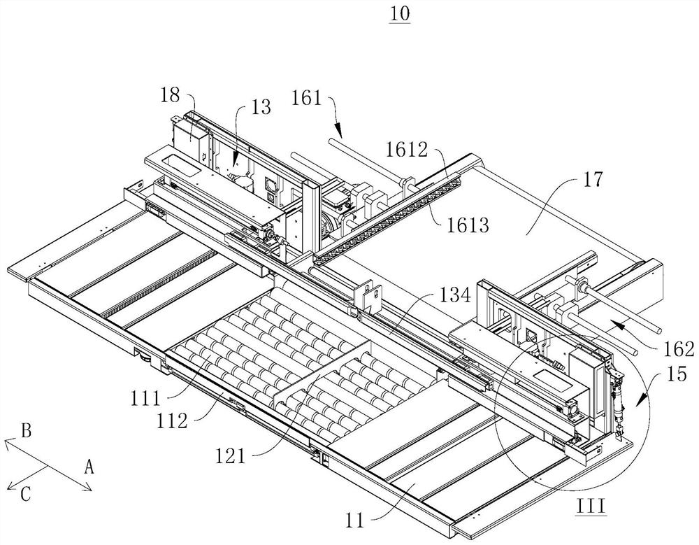
[0037] see figure 1 , figure 1 It is a schematic diagram of the three-dimensional structure of the stacking device 10 provided by the first embodiment of the present invention. figure 1 Among them, the direction indicated by the arrow A is the first direction A, the direction indicated by the arrow B is the second direction B, and the direction indicated by the arrow C is the third direction C.

[0038] The first embodiment of the present invention provides a stacking device 10 , the stacking device 10 has the characteristics of high utilization rate of the space of the compartment 90 and is not easy to squeeze the goods 80 . The stacking device 10 can be applied to a vehicle loading machine 100, a vehicle loading system, a logistics storage system, and the like.

[0039] The structural composition, working principle and beneficial effects of the stacking device 10 provided by the first embodiment of the present invention will be described in detail below.

[0040] see fig...

no. 2 example

[0085] see Figure 4 , Figure 5 and Image 6 , Figure 4 It is a schematic perspective view of the three-dimensional structure of the vehicle loading machine 100 provided in the second embodiment of the present invention. Figure 5 It is a schematic diagram of the side structure of the vehicle loading machine 100 provided in the second embodiment of the present invention. Image 6 It is a three-dimensional schematic diagram of the connection between the cargo conveying line 20 of the vehicle loader 100 and the stacking device 10 provided by the second embodiment of the present invention.

[0086] The second embodiment of the present invention provides a vehicle loading machine 100. The vehicle loading machine 100 adopts the stacking device 10 provided by the first embodiment of the present invention. The vehicle loading machine 100 also has a compartment 90 with a high space utilization rate and is not easy to squeeze. Features of Press Cargo 80. The vehicle loading mach...

no. 3 example

[0094] see Figure 7 , Figure 7 It is a schematic flowchart of the loading method provided by the third embodiment of the present invention.

[0095] The third embodiment of the present invention provides a vehicle loading method, which is applied to the stacking device 10 or the vehicle loading machine 100 mentioned in the above embodiments, which also has a high space utilization rate of the compartment 90 and is not easy to squeeze Cargo 80 features.

[0096] It should be noted that the basic principles and technical effects of the loading method provided in this embodiment are the same as those of the above-mentioned embodiment. For a brief description, the part not mentioned in this embodiment can refer to Corresponding content.

[0097] The loading method includes:

[0098] Step S101: Move the cargo 80 along the first direction A or the second direction B according to the horizontal position data and the preset stacking data, so that both ends of the row of cargo 80...


PUM


Abstract

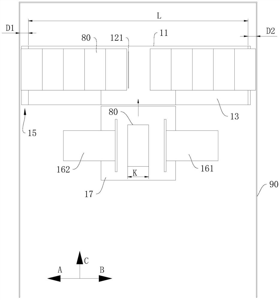
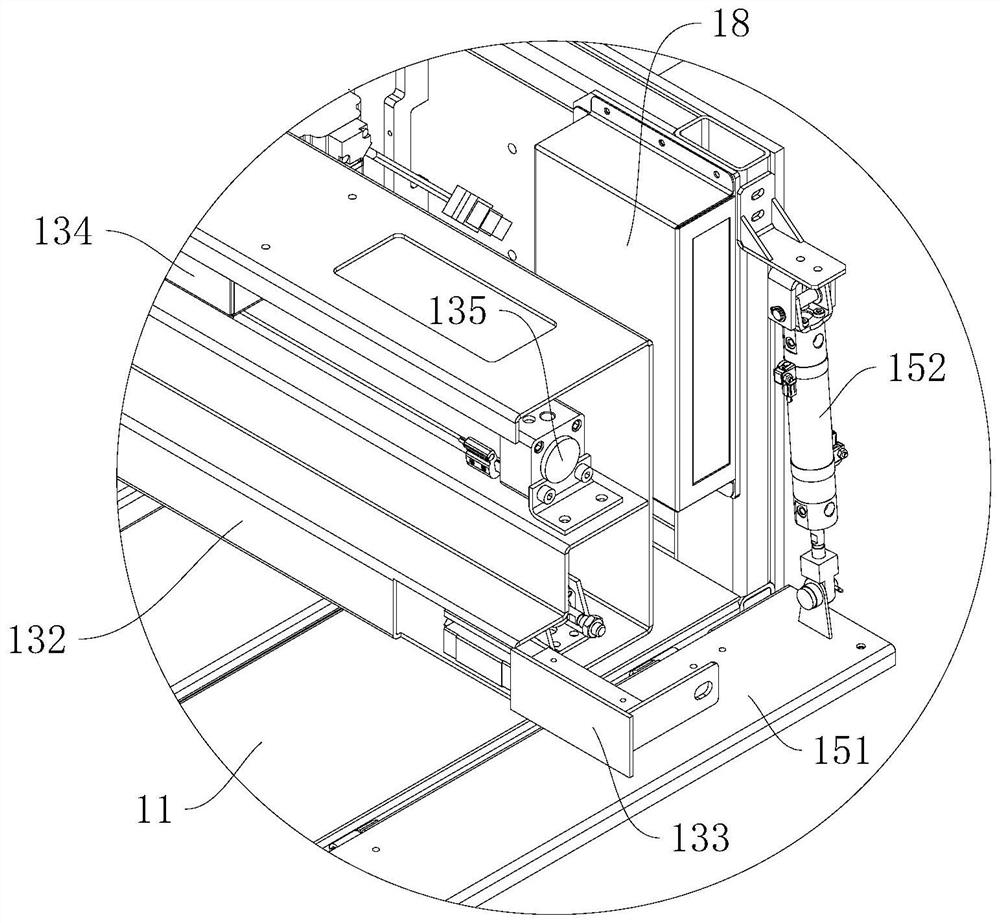
The invention discloses a stacking device, a loading machine and a loading method, and relates to the technical field of loading. The stacking device comprises a stacking platform, a toggle mechanism,a push-out mechanism and a stacking width measuring mechanism in communication with the toggle mechanism. The stacking platform is used for receiving and carrying goods. The stacking width measuringmechanism can measure the distances between the two ends of the stacking platform in the first direction and the left and right side walls of a carriage respectively, and generating transverse position data. The toggle mechanism is arranged in the middle of the stacking platform, and can toggle the goods in the first direction or in the second direction opposite to the first direction according tothe transverse position data and preset stacking data, so that the two ends of the goods arranged in a row abut against the left side wall and the right side wall of the carriage. The push-out mechanism can push the goods out of the stacking platform in the third direction to stack the goods in a stacking position, wherein an included angle is formed between the first direction and the third direction. The stacking device, the loading machine and the loading method have the characteristics that the space utilization rate of the carriage is high, and the goods are not easy to extrude.

Description

technical field [0001] The invention relates to the technical field of vehicle loading, in particular to a stacking device, a vehicle loading machine and a vehicle loading method. Background technique [0002] In the field of production, warehousing and logistics, automatic loading equipment has become a research and development hotspot at home and abroad. In closed compartments such as container vehicles and fenced vehicles, in order to avoid collisions between the loading equipment and the compartment, the narrow stacking space has great restrictions on the operation of the loading equipment, and also requires high loading accuracy. Especially when stacking box-type cargo, since the box-type cargo cannot be squeezed and deformed, how to avoid squeezing the cargo and improve the utilization rate of the compartment space has become a challenge. [0003] In view of this, it is particularly important to develop and design a stacking device, a loading machine and a loading met...

Claims


Application Information

Patent Timeline
Patent Type & Authority Applications(China)
IPC IPC(8): B65G67/04B65G57/03B65G43/00B65G13/00B65G47/88B65G47/82
CPCB65G67/04B65G57/03B65G43/00B65G13/00B65G47/8823B65G47/82
Inventor 许大红石江涛张杰翟新蒋玉鸣
Owner CHINA HEFEI TAIHE OPTOELECTRONICS TECH
Learn More