Roller forming device for highway construction

A rolling forming, road technology, applied in the direction of road, road, road repair, etc., can solve the problems of steering trouble, pressing device without steering mechanism, etc.

Active Publication Date: 2020-10-27
李云飞
View PDF8 Cites 2 Cited by
  • Summary
  • Abstract
  • Description
  • Claims
  • Application Information

AI Technical Summary

Problems solved by technology

[0005] In order to overcome the disadvantage that the pressing device does not have a steering mechanism and the steering is troublesome during road construction, the technical problem of the present invention is to provide a roll forming device for road construction with simple operation and convenient steering

Method used


Image

  • Roller forming device for highway construction
  • Roller forming device for highway construction
  • Roller forming device for highway construction

Examples


Embodiment 1

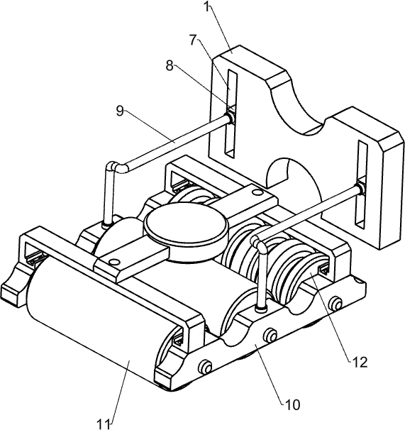
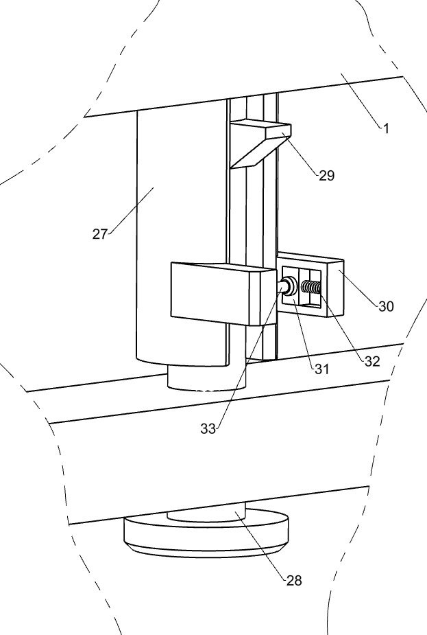
[0022] A road construction roll forming device, such as Figure 1-4 As shown, it includes a base plate 1, a first roller 2, a handle 3, a driving assembly, a rolling assembly and a lifting assembly. The lower end of the base plate 1 is symmetrically rotated with the first roller 2, and the right side of the base plate 1 is fixed by bolts. There is a handle 3, the right side of the base plate 1 is provided with a drive assembly powered by a motor, the left side of the base plate 1 is provided with a rolling assembly that rolls the road surface by rolling, and the middle of the base plate 1 is provided with a rolling assembly that rotates to make the road surface roll. A lifting component that lifts components up and down.

[0023] When the device is used for road rolling forming work, the driving component is controlled to work, and the lifting component is driven to rotate, so that the rolling component is lowered. When the bottom of the rolling component is close to the groun...

Embodiment 2

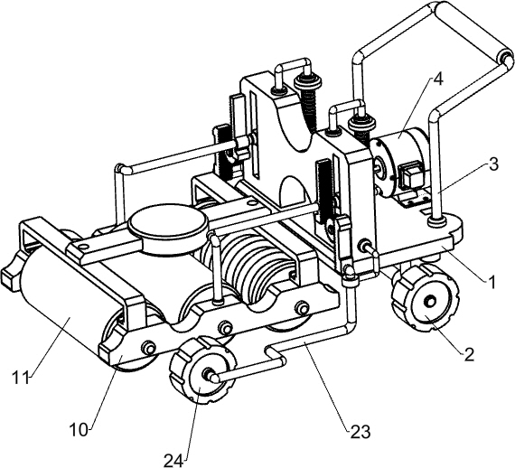
[0031] On the basis of Example 1, such as figure 1 , 5 Shown in and 6, also include the first tooth bar 21, guide sleeve 22, the second special-shaped bar 23, the second roller 24, the second tooth bar 25 and full gear 26, the first special-shaped bar 9 right parts are all fixed by bolts The first tooth bar 21 is connected, and the front and rear sides of the base plate 1 are fixedly connected with guide sleeves 22 by bolts. The second roller 24, the second special-shaped rod 23 right side tops are fixedly connected with the second rack 25 by bolts, and the left side of the base plate 1 is provided with a full gear 26 in a symmetrical rotation type before and after, and the full gear 26 is connected with the first rack 21 and the second rack 26. Two tooth racks 25 mesh.

[0032]In the process of controlling the downward movement of the rolling assembly, the downward movement of the first special-shaped rod 9 will drive the first rack 21 to move downward, causing the full gea...


PUM


Abstract

The invention relates to a forming device, and particularly relates to a roller forming device for highway construction. A technical problem to be solved in the invention is to provide the highway construction roller forming device which is simple to operate and convenient to steer. The roller forming device for highway construction comprises a bottom plate, first rollers, a grip, a driving assembly, a rolling assembly, and a lifting assembly, wherein the first rollers are symmetrically and rotatably mounted on the bottom plate; the grip is mounted on the bottom plate; the driving assembly ismounted on the bottom plate; the rolling assembly is mounted on the bottom plate; and the lifting assembly is mounted on the bottom plate. In the invention, rolling forming work of a road is completedthrough the rolling assembly; the driving assembly works to drive the lifting assembly to move so that the rolling assembly is ensured to abut against the ground, and the rolling assembly is driven by the lifting assembly to ascend and descend; and the position of a second roller is moved, the moving mode of the device is changed according to conditions, a moving friction force during non-workingis reduced, and the device is more convenient to move.

Description

technical field [0001] The invention relates to a forming device, in particular to a rolling forming device for road construction. Background technique [0002] Highway is a modern term. It is a public road where cars can be driven. Many vehicles such as cars, bicycles, rickshaws, horses, and pedestrians can walk. There were no restrictions on the early roads, most of which were simple roads. Later, different roads had different restrictions; due to the increasingly developed traffic, more and more roads were used with restrictions, especially some roads were dedicated to cars, and expressways were developed. Type, designed for full-enclosed use in cars. [0003] The patent authorization announcement number is CN208618227U, which discloses a traffic engineering highway construction extrusion molding device, including a base plate, the bottom of the base plate is movably connected with a gear belt, and one side of the upper surface of the base plate is fixedly connected with...

Claims


Application Information

Patent Timeline
IPC IPC(8): E01C19/24
CPCE01C19/24
Inventor 李云飞
Owner 李云飞
Why Eureka
Try Eureka